Industrial Process Chiller Selection: How to Match Cooling Capacity, Flow, and Temperature to Your Production Line
Updated September 23, 2026.
An industrial process chiller should be selected from the process it must protect, not from a nominal tonnage copied from a previous project. The useful starting point is a defined process load, fluid, supply-and-return temperature, flow rate, operating profile, and consequence of a cooling interruption. Once those inputs are clear, the equipment configuration, heat-rejection method, controls, and redundancy can be compared on the same basis.
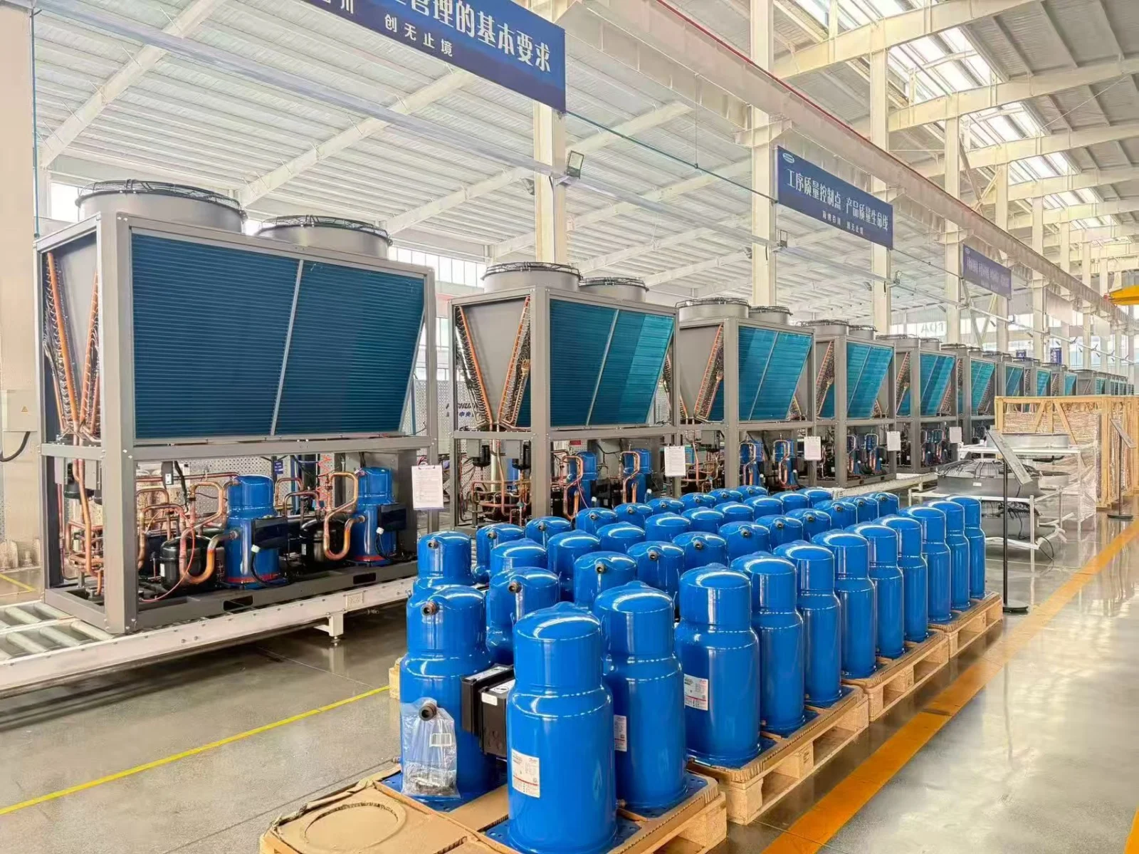
This guide is for plant engineers, contractors, distributors, and project buyers evaluating chilled-water or process-fluid cooling for manufacturing and technical equipment. It is not a model selection or a substitute for the responsible engineer’s design review. The final setpoint, fluid, capacity, electrical data, operating envelope, and protection functions must be confirmed against the selected unit and the actual process.
Key takeaways
- Flow, fluid properties and temperature difference establish the heat removed from the process loop. Compare that required duty with the chiller’s available capacity at the same project conditions.
- Define whether the equipment is cooling a direct process loop or a secondary chilled-water loop, and identify the heat exchanger, fluid boundary and contamination risk.
- Ask every supplier for the same entering/leaving temperatures, flow, fluid concentration, ambient condition, input power, operating limits and failure response.
- A nominal capacity label, even when it matches the design load, cannot establish production resilience; redundancy, pump proof, controls and commissioning evidence must be specified separately.
The short answer: select the process first, then the chiller
A useful industrial process chiller brief answers six questions:
- How much heat must be removed at the design and peak operating conditions?
- What supply temperature, return temperature, flow, and stability does the process require?
- Is the loop water, glycol solution, or another approved process fluid?
- Will the chiller run continuously, intermittently, or with frequent load changes?
- What happens to production, equipment, and product quality if cooling is lost?
- What must the chiller report, alarm, and interlock with the process controls?
The SongXin industrial process chiller page describes the product category for manufacturing, production lines, equipment rooms, and technical processes where cooling is tied to equipment protection and production continuity. That is a different reader task from the site’s existing air-cooled versus water-cooled chiller comparison, which focuses on the heat-rejection architecture. This article starts on the process side: what the loop must do, and what evidence a supplier should provide.
1. Define the process loop before choosing capacity
An industrial process chiller removes heat from a circulating fluid used to cool equipment or a process. In a shared-fluid arrangement, fluid from the chiller travels through the process cooling circuit. An isolated arrangement uses a heat exchanger to separate the two fluids. Primary/secondary pumping alone does not provide that separation. Identify open tanks, contamination risks and permitted wetted materials before deciding which arrangement fits the process.
Comfort cooling usually begins with a building load and indoor conditions. Process cooling begins with a machine, material, fluid, or production step whose temperature affects operation. Examples include a mold, hydraulic circuit, spindle, laser, power-electronics cabinet, production line, or controlled process bath.
Write the process boundary in one paragraph. Identify:
- The equipment or process that creates the heat.
- The point where the cooling fluid enters and leaves the process.
- The allowed supply-temperature range and the expected return temperature.
- The minimum and maximum flow rate, including turndown conditions.
- The fluid composition, concentration, cleanliness, and compatibility requirements.
- The operating hours, start-up pattern, ambient range, and seasonal conditions.
- The response required after a low-flow, high-temperature, pump, or power fault.
This boundary prevents a common procurement error: treating a chiller’s cooling capacity as if it were the same thing as the process’s usable cooling. A unit can have enough nominal capacity and still be unsuitable if its minimum flow, leaving-water temperature, control response, fluid compatibility, or pressure duty does not match the loop.
2. Calculate the design cooling duty from measured or defensible inputs
For a single-phase water loop, a first-pass heat-removal calculation can be written as:
Q (kW) = flow (m³/h) × density (kg/m³) × specific heat (kJ/kg·K) × ΔT (K) ÷ 3,600For water near ordinary chilled-water conditions, density and specific heat can be treated as approximate inputs for an early estimate. Use the actual fluid properties for glycol or another process fluid; both density and specific heat change the result. If the process has multiple branches, calculate each branch and define the simultaneous operating case rather than adding every nameplate value automatically.
Illustrative calculation — not a product selection
Assume a water loop has a flow of 35 m³/h, a return temperature of 12°C, and a supply temperature of 7°C. With an illustrative density of 1,000 kg/m³ and specific heat of 4.18 kJ/kg·K:
35 × 1,000 ÷ 3,600 × 4.18 × (12 − 7) = approximately 203 kWIf the project team documents a 10% allowance for a defined measurement or future-load uncertainty, the planning value becomes approximately 223 kW. That allowance is an assumption for this example, not a universal sizing rule. State what the allowance covers, and do not use it to hide an unknown process load. The final selection should show the design and peak cases, entering and leaving conditions, fluid properties, and the supplier’s selected output at those conditions.
Add pump heat transferred to the fluid and pipe heat gain only if they fall inside the load boundary and are not already counted. A heat exchanger’s approach temperature is not an extra heat load: it is a temperature difference needed to transfer heat. For example, a process loop needing 7°C supply may require colder chiller water when an isolating exchanger is used. Select the chiller at that colder condition and calculate the exchanger and pump duties separately.
3. Treat temperature, flow, and stability as separate requirements
“The chiller provides 7°C water” is not a complete process specification. A process may need a narrow supply-temperature band, a minimum circulation rate, a maximum rate of change, or a stable pressure at the equipment connection. Record each requirement separately.
REFERENCE TABLE · On small screens, scroll horizontally to read all columns.
| Input to confirm | Why it changes the selection | Evidence to request |
|---|---|---|
| Supply temperature and allowed variation | Determines the refrigeration and control operating range. | Selection report showing the stated setpoint and tolerance. |
| Return temperature and design ΔT | Drives the heat-removal calculation and control response. | Process heat-load calculation with design and peak cases. |
| Minimum, normal, and maximum flow | Affects heat transfer, pump duty, bypass logic, and low-flow protection. | Pump curve, flow range, and process-valve arrangement. |
| Fluid and concentration | Changes heat capacity, viscosity, pressure loss, and material compatibility. | Fluid data sheet, concentration target, and approved materials. |
| Connection pressure and loop arrangement | In a closed loop, the pump overcomes circuit losses; static elevation is not simply added as circulation head. Open arrangements require their actual elevation duty. | Piping schematic, pressure-loss calculation and system pressure limits. |
| Stability or ramp requirement | Determines sensor location, control tuning, and buffer volume. | Control narrative and acceptance test method. |
If the loop uses glycol, do not reuse a water-only flow calculation without recalculating the fluid properties and pressure loss. Where a pipe surface is below the surrounding air’s dew point, assess insulation and vapor sealing to control condensation. Separately, confirm the fluid concentration and protection sequence for the lowest expected fluid and ambient temperatures, including shutdown conditions.
This is not a cosmetic correction. Dow’s DOWFROST engineering guide publishes density, specific heat and viscosity tables that change with glycol concentration and temperature. Johnson Controls likewise states in its centrifugal-chiller flow-limit guide that its published limits are for water and that other fluids such as glycol need equipment-specific engineering limits. Use those sources as a reason to request a named-fluid selection—not as universal correction factors for every glycol product.
The mechanism is practical: a lower specific heat removes less heat at the same mass flow and temperature difference, while higher viscosity increases pressure loss and can reduce the flow a pump actually delivers. That is why changing fluid concentration can change both chiller capacity and pump selection.
No capacity, efficiency, leaving-temperature or operating-range value in this guide should be read as a published rating for a specific SongXin model. The supplier’s selection report must state the model, rating conditions and applicable tolerances.
Illustrative capacity schedule for an RFQ
The following is a comparison format, not a model rating. It shows how the same request can expose a normal case, a peak case and a fluid-property case before quotations are compared.
REFERENCE TABLE · On small screens, scroll horizontally to read all columns.
| Case | Flow | Fluid and temperatures | Screening result or requested output | Decision use |
|---|---|---|---|---|
| Normal water loop | 35 m³/h (154 US gpm) | Water, 7°C supply / 12°C return | Approximately 203 kW from the worked example | Check normal-load control and turndown. |
| Coincident peak | 42 m³/h (185 US gpm) | Water, 7°C supply / 13°C return | Approximately 293 kW required; supplier to select against this duty | Check whether peak capacity and high-ambient output remain available. |
| Glycol loop | 35 m³/h (154 US gpm) | Named glycol concentration, 2°C supply / 7°C return | Supplier to recalculate capacity, viscosity and pressure loss | Check whether the pump, heat exchanger and chiller selection change. |
For the peak row, the screening value uses the same illustrative water properties: 42 × 1,000 ÷ 3,600 × 4.18 × 6 ≈ 293 kW. It is not a substitute for the actual fluid data or a selected-unit rating.
4. Size for the operating profile, not only the peak nameplate
Industrial loads often change as machines start, stop, change recipe, or operate in parallel. Request a load profile with at least:
- Minimum stable load.
- Normal production load.
- Coincident peak load.
- Start-up or pull-down load.
- Ambient conditions associated with each case.
- Expected future machines or production shifts, identified as a separate assumption.
This profile helps the team compare compressor staging, variable-flow behavior, buffer volume, and control response. A very large unit may satisfy a peak number but cycle or operate inefficiently at the normal load. A small unit may run continuously at full output and still fail during a high-ambient or simultaneous-production condition. The appropriate answer depends on the selected equipment’s operating envelope and the process’s acceptable risk, not on a generic “oversize by 10%” instruction.
For a critical production line, define the consequence of failure before deciding on redundancy. Possible arrangements include a standby chiller, multiple modules, a second pump, a bypass, or a temporary connection point. “N+1” is not self-explanatory: state whether it applies to chillers, compressors, pumps, power supplies, or complete cooling paths, and define the load that must remain available after one component is unavailable.
Four selection failures that a nominal capacity will not reveal
- Minimum-flow mismatch: the chiller has enough peak capacity, but its minimum flow is higher than the process can maintain, so the loop needs a bypass, buffer or different control arrangement.
- Fluid-property mismatch: the same volumetric flow with glycol produces a different heat-removal and pressure-loss result, which can change both capacity and pump duty.
- Non-coincident branches: the stated 35 m³/h is a total of branches that never run together, so adding every nameplate load overstates the simultaneous case; the opposite mistake can understate a recipe or shift overlap.
- High-ambient derating: an air-cooled unit meets the nominal condition but loses available capacity at the project’s actual design ambient, leaving no margin for the peak process case.
5. Choose air-cooled or water-cooled from the site constraints
Air-cooled and water-cooled configurations are heat-rejection choices, not substitutes for a process brief. Compare them after the required process duty and operating conditions are fixed.
An air-cooled arrangement may simplify a site without cooling-tower water, but the selection still needs the design ambient temperature, airflow clearance, noise limits, service access, and high-ambient capacity. A water-cooled arrangement may fit a central plant or an existing condenser-water system, but it adds water quality, tower or dry-cooler coordination, pump duty, treatment, and maintenance responsibilities.
Compare the air-cooled chiller and water-cooled arrangements against the same process brief. A screw compressor describes compressor technology, not the heat-rejection method; those are separate selection decisions. The same process duty can lead to different equipment choices when utilities, ambient conditions and service resources change.
6. Match the chiller package to the process risk
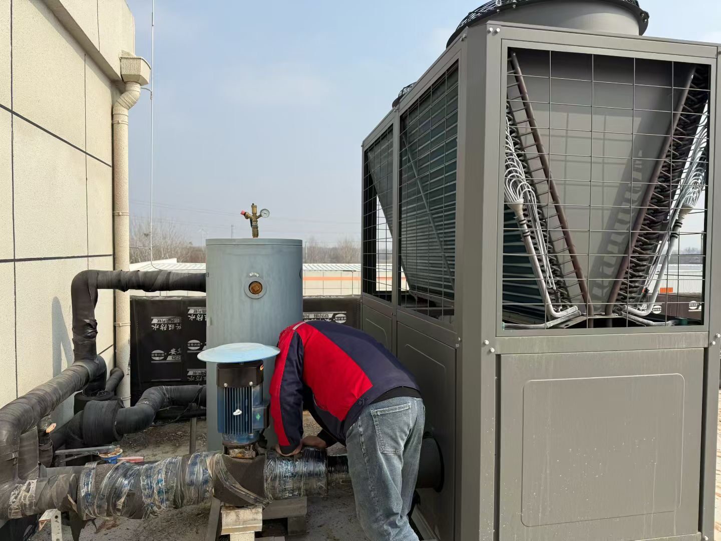
The chiller is part of a cooling path. Review the following package items together:
- Process pump duty, standby philosophy, and variable-flow or constant-flow arrangement.
- Expansion vessel, buffer tank, air separator, strainers, and fill/drain provisions.
- Flow switch or flow sensor location and the action taken on low flow.
- Temperature sensor locations at the chiller, common header, and process connection.
- Heat exchanger arrangement where the process fluid must be isolated from the chiller loop.
- Insulation, vapor sealing, freeze protection, and condensate management.
- Electrical supply, emergency stop logic, restart behavior, and safe shutdown.
- Access for filter cleaning, pump service, refrigerant service, and component removal.
Do not let a packaged quotation conceal a missing process accessory. Ask the supplier to mark the equipment boundary and the field-installed boundary on the piping and control drawings.
7. Make the controls and alarms testable
At minimum, the control narrative should show how the system responds to:
- Normal enable and disable commands.
- Process supply-temperature deviation.
- Low flow or a failed pump.
- High return temperature or an approaching capacity limit.
- High or low fluid pressure where applicable.
- Loss of communication with the plant control system.
- Power recovery and manual reset requirements.
List each alarm with its priority, delay, latching behavior, local indication, remote point, and operator action. A statement such as “BMS compatible” is not a control specification. The selected chiller, pump package, sensors, gateway, and plant controller must have an agreed points list and responsibility matrix.
A practical RFQ brief for an industrial process chiller
Send the supplier a brief that includes the following fields:
REFERENCE TABLE · On small screens, scroll horizontally to read all columns.
| RFQ field | Example of a useful entry |
|---|---|
| Application | Injection-molding machine cooling, electronics line, food process, or another defined duty. |
| Design duty | Normal and peak heat load in kW, with the calculation boundary stated. |
| Fluid | Water or named glycol solution, concentration, cleanliness, and compatibility constraints. |
| Temperatures | Supply, return, allowable variation, and start-up/pull-down condition. |
| Flow | Minimum, normal, and maximum flow in m³/h or another stated unit. |
| Heat rejection | Air-cooled or water-cooled preference, ambient or condenser-water conditions. |
| Operating profile | Hours, shifts, load changes, and required continuous operation. |
| Reliability | Required standby capacity, bypass, temporary connection, and restart behavior. |
| Controls | Local interface, remote points, alarms, interlocks, and network responsibility. |
| Site limits | Electrical supply, footprint, noise, lifting route, service clearances, and ambient. |
| Deliverables | Selection report, datasheet, wiring/controls points, drawings, test plan, and manuals. |
Ask for the selected capacity and input power at the stated conditions, not only a model number. Ask the supplier to identify exclusions, assumptions, minimum flow, operating limits, fluid restrictions, and the evidence needed for commissioning.
Final selection checklist
Before placing an order, confirm that:
Frequently asked questions
How do I calculate an industrial process chiller’s required capacity?
For a single-phase water loop, use flow × density × specific heat × temperature difference ÷ 3,600 to obtain an early kW estimate. Then separate simultaneous process load, pump or heat-exchanger heat, fluid-property changes and documented uncertainty before asking for a model selection.
Does glycol change the chiller size?
Yes. Glycol changes density, specific heat, viscosity and pressure loss. The supplier should recalculate capacity, flow, pump duty, heat-exchanger performance and material compatibility at the stated concentration rather than applying a water-only result.
What does N+1 mean for process cooling?
It means one defined component or cooling path can be unavailable while the agreed load remains served. The RFQ must say whether N+1 applies to chillers, compressors, pumps, power supplies or the complete process-cooling path.
Should I choose an air-cooled or water-cooled process chiller first?
No. Define the process duty and operating conditions first, then compare heat rejection using ambient, utilities, water treatment, noise, access, maintenance and high-ambient capacity evidence.
For a project-specific review, send the process description, load calculation, fluid data, temperature and flow schedule, site conditions, control requirements, and the required delivery documents with your SongXin HVAC selection enquiry. The industrial process chiller product page can help the project team identify the product category; the final configuration still needs to be matched to the actual process and verified before procurement.