HVAC Systems for Semiconductor Cleanrooms: Design Checklist
A traceable design chain from process risk to acceptance testing — for fab owners, MEP teams, and procurement teams preparing an RFQ.
HVAC systems for semiconductor cleanrooms need a process contamination-control basis. Do not select airflow or filtration alone. Define the threat, source, zone interfaces, operating state, and test.
The short answer is to build one traceable chain:
A defensible specification links every step. ISO 14644-1 particle class does not control AMC. A HEPA or ULPA label does not prove ceiling integrity. A figure from another facility is not automatically this fab’s setpoint.
This is a pre-design and RFQ checklist. The owner, codes, hazard analysis, tool data, and qualified calculations set values. This checklist connects each requirement to a mechanism, test, alarm, and failed-state response.
Key takeaways for semiconductor cleanroom HVAC
- Freeze the process basis before selecting airflow, filters, or capacity.
- Separate ISO 14644-1 particle class from owner-specific AMC limits.
- Pair media certificates with an installed integrity test.
- Map every requirement to its operating state, limit, test, and owner.
Verified semiconductor cleanroom HVAC reference values
These official values support comparisons; none is a project setpoint.
| Reference item | Verified value | Buyer decision | Not proven |
|---|---|---|---|
| EPA HEPA minimum | At least 99.97% removal at 0.3 µm | Media baseline for an RFQ | Installed integrity. |
| EPA HEPA reference size | 0.3 µm is the cited worst-case (MPPS) | Keeps ratings tied to a test reference | Room particle or AMC limit. |
| EPA MERV range | MERV reports capture between 0.3 and 10 µm | Separates MERV comparisons from HEPA claims | Cleanroom classification. |
Filter ratings apply to a defined test. The delivered room also needs an agreed challenge aerosol, upstream concentration, scan method, acceptance rule, repair policy, and report. Request the factory certificate and installed test record.
Public reference values that remain reference-only
Public figures are not owner requirements.
An LBNL field study measured five ISO Class 4 rooms at 385 to 678 h⁻¹ and 0.30 to 0.60 m/s (59 to 118 feet per minute). Its ISO Class 5 observations were 98 to 479 h⁻¹ and 0.10 to 0.40 m/s (20 to 79 feet per minute). These are field observations, not standard-defined bands or semiconductor setpoints.
NASA’s MSFC-STD-246E includes a 12.5 Pa (0.05 inch water gauge) minimum pressure differential in its applicable controlled environments. Its airflow-test method measures 30 to 50 cm (12 to 20 inches) from the filter or diffuser face on an approximately 0.5 m² (6 square feet) grid for unidirectional certification. These are NASA criteria, not semiconductor-fab defaults (NASA MSFC-STD-246E).
A NIST assessment describes 35% to 65% RH in its semiconductor-fab background. Use it only as planning context; process, ESD, condensation, and tool limits may be narrower (NIST, Final Programmatic Environmental Assessment for Semiconductor Fabs).
Use a borrowed value only when its clause, boundary, operating state, and process-owner approval are documented.
What semiconductor cleanroom HVAC design means
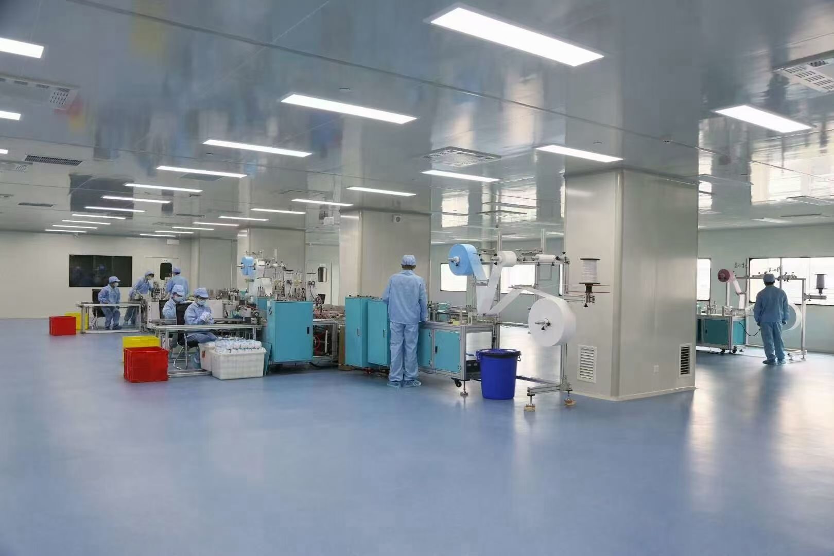
Semiconductor cleanroom HVAC design coordinates particle and AMC control with thermal loads, room pressure, airflow, and exhaust replacement.
“Clean” is not one variable. A room can pass its particle class yet fail when AMC is above the owner limit, a filter seal leaks, local recirculation forms, or air transfers from a dirtier zone.
Start with four owner documents:
- Process and contamination-risk matrix.
- Room data sheet for each controlled zone.
- Tool utility and exhaust schedule.
- Verification plan for as-built, at-rest, and operational states.
ISO 14644-1 classifies airborne-particle concentration at defined threshold sizes. It does not characterize physical, chemical, radiological, or viable nature. Particle counters cannot identify AMC because they measure a different property, so an ISO class is not AMC compliance.
For chemical contamination, ISO 14644-8 provides an assessment framework and SEMI F21 addresses microelectronics. The owner still sets substances, locations, time basis, and limits.
Two adjacent standards can affect the package without setting particle limits: IEC 61340-5-1:2024 covers applicable ESD control programs, while IEC 62443-3-3 covers IACS system security. They do not set cleanroom HVAC acceptance values.
Semiconductor cleanroom HVAC design checklist
Use this list at design review and RFQ release; each item needs named evidence.
1Freeze the contamination-control basis
- List process steps, exposed product states, critical zones, particle sizes, and AMC substances.
- Separate surface, ESD, vibration, magnetic, biological, and HVAC requirements.
- Assign every limit to the process owner, tool supplier, EHS team, code authority, or facility.
2Define zones and compliance states
- Record each room’s ID; function; dimensions; occupancy; schedule; particle class; and operating state.
- Map airlocks; gowning; corridors; chases; subfab areas; returns; and mini-environments.
ISO 14644-4 covers requirements through start-up. A class without an operating state is incomplete because people and tools change particle generation.
3Map contamination routes
For each risk, record its source; route; receptor; control; response; and acceptance evidence. Cover people and materials; tools and chemicals; outdoor and adjacent air; construction; fans; and maintenance.
4Coordinate tool exhaust and makeup air
- Obtain minimum; normal; maximum; purge; startup; standby; and emergency exhaust by tool.
- Separate general; acid; alkaline; solvent; toxic; combustible; and heat exhaust where required.
- Calculate replacement air for each operating mode and door condition.
Exhaust and makeup air set the pressure balance; the sequence must coordinate transfer paths and alarms.
5Choose the airflow concept
- Select unidirectional, mixed, ballroom, bay-and-chase, or mini-environment flow from process risk and geometry.
- Draw supply, return, transfer, exhaust, and leakage paths in section.
- Use visualization or validated modeling for stagnant zones, short-circuiting, and cross-contamination.
ACH is a volume ratio. It does not prove local direction, uniformity, filter coverage, heat-plume capture, or product exposure. A copied ACH can fail because it ignores source location and return geometry.
6Build filtration as a system
- Record grade, test method, face flow, initial/final pressure drop, construction, and compatibility.
- Pair the element with stages; FFU/central layout; housing; seals; clamping; scan access; and service rules.
- Require factory certificates and an installed integrity test after construction and replacement.
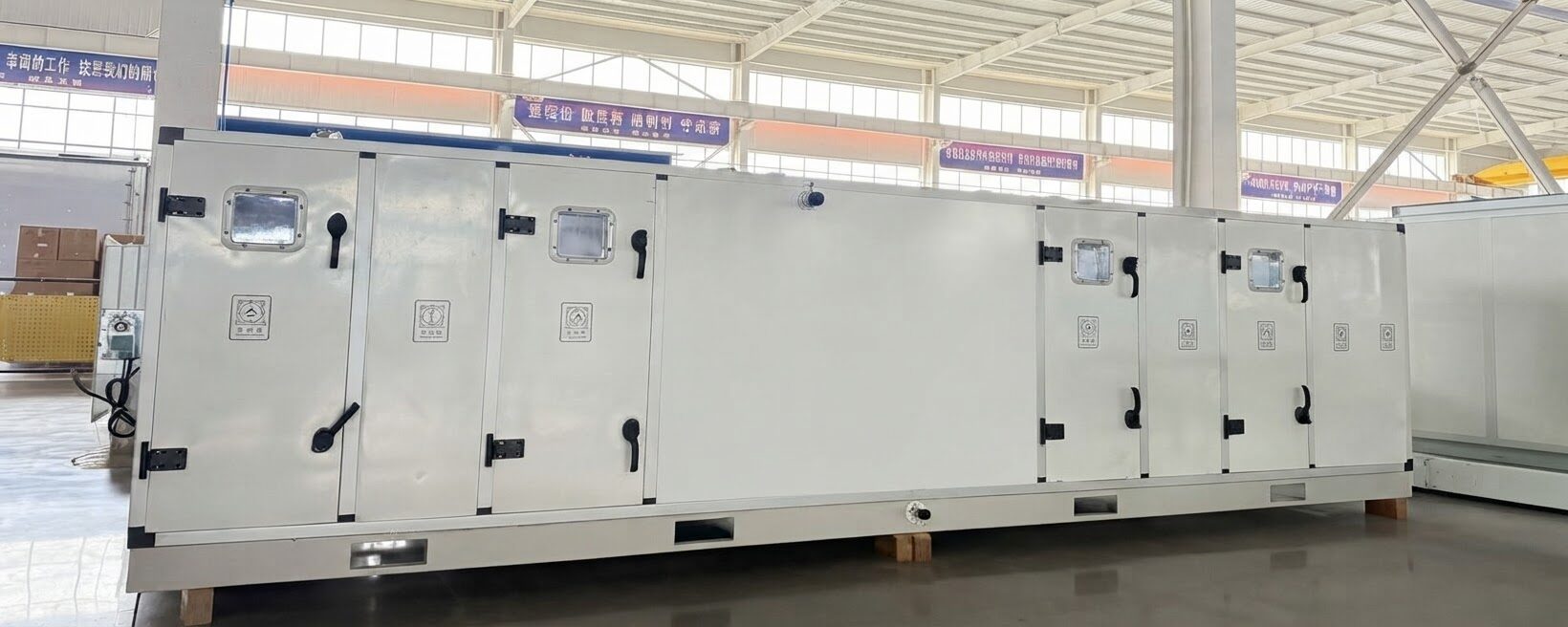
Higher media efficiency can increase resistance, fan duty, energy, noise, and replacement constraints when pressure-drop or service limits are tight. Select the simplest verified system that controls process risk and fits the TCO model. See SongXin’s Air-Side Equipment range for filtration-stage air handling components.
7Separate particle and AMC control
- Create separate particle and AMC schedules with sizes or substances, units, locations, states, methods, and limits.
- Map molecular sources and define adsorbent capacity, bypass, breakthrough, and replacement basis before media selection.
HEPA/ULPA ratings concern particles; they do not demonstrate gaseous AMC removal. For a gaseous target or upstream source, source capture, chemistry control, segregation, or gas-phase media may be needed.
8Set temperature, humidity, and sensible load
- Record temperature; RH/dew-point; tolerance; rate-of-change; mapping; and recovery limits.
- Resolve ESD, hygroscopic materials, resist, corrosion, condensation, and garments against process limits.
- Calculate gains from people; lights; tools; FFUs; motors; utilities; envelope; makeup air; and ducts by state.
9Define room pressure
- Draw the pressure cascade and reference nodes for every opening and door state.
- Reconcile product protection with hazardous-material containment and code requirements.
- Calculate leakage/transfer and record sensor range, accuracy, zeroing method, alarm delay, deadband, and trend interval.
Positive pressure may protect product, while a hazardous source may need inward flow. The owner, EHS authority, process designer, and code professional must resolve the hierarchy.
10Design for clean maintenance
- Provide service-side access to fans, coils, dampers, sensors, filters, and drains.
- Use low-shedding, cleanable, compatible exposed materials and define recertification after intrusive work.
If a repair exposes a critical zone, the maintenance event becomes a production risk.
Engineering basis for semiconductor cleanroom HVAC airflow
A usable basis maps each requirement to five fields.
“Maintain pressure” is incomplete without reference spaces, direction, range, and state. Add alarm logic, test method, and owner.
Use a cleanroom air-balance equation
Use this equation for each zone and operating mode.
Recirculated air affects filtration, mixing, and heat transport, but it does not replace process exhaust. Keep one flow schedule and one unit system.
Illustrative makeup-air calculation
This is an author-created sizing example. It is not a SongXin project result.
Substitution: 18,000 + 1,500 − 500 = 19,000 m³/h (11,183 CFM).
If the makeup-air unit supplies 20,000 m³/h (11,772 CFM), arithmetic spare is 1,000 m³/h (589 CFM), or 5.3%. Recommendation: treat this as a starting allowance; test exhaust, door, standby, and emergency states before fixing capacity or pressure setpoints.
Calculate cooling by state, not by one peak total
Compare production, standby, maintenance, startup, and failure states. Obtain each tool’s heat split to room air, exhaust, and process water. Counting one heat source twice overstates HVAC load.
For lifecycle procurement, start with a 12-month inspection interval and 24-month replacement review. Revise both from measured loading and the owner’s total cost of ownership (TCO) model; they are not universal limits.
Link every control point to a response
A monitoring point without an action plan is only a data logger. The sequence needs:
- normal range, alert level, action level, and alarm delay;
- sensor validation and commanded response;
- escalation owner and production notification;
- failed-sensor safe state and reset authority.
ISO 14644-2 sets minimum requirements for a particle-performance monitoring plan. Use it alongside, not instead of, required certification tests. SongXin’s Control & Automation Solution covers monitoring and BMS integration for continuous 24/7 sensor logging.
Semiconductor cleanroom HVAC redundancy and controls
“N+1” is not a complete redundancy specification. Define duty, component boundary, shared dependencies, switchover state, and acceptance test.
Use a failure matrix before choosing redundant equipment:
| Failure | Safe condition | Response to specify | Acceptance evidence |
|---|---|---|---|
| One recirculation fan or FFU fails | Local particle and airflow risk remains within the accepted response plan | Fan zoning, spare duty, isolation, alarm, and repair access | Controlled failure test plus particle/velocity trend. |
| One makeup-air unit fails | Exhaust replacement and pressure direction remain safe or the process enters an accepted shutdown | Standby capacity, common-duct isolation, coordinated exhaust turndown | Unit-loss test with pressure and flow trends. |
| One cooling source or pump fails | Critical temperature remains within the owner-approved ride-through or recovery envelope | Redundant source/pump, thermal buffer, staged tool response | Failure and recovery trend at a representative load. |
| One pressure sensor fails | Control does not drive the room in the wrong direction | Sensor validation, voting or fallback logic, alarm | Simulated sensor failure and sequence verification. |
| Controls network or power fails | Dampers, fans, exhaust, and alarms move to defined safe states | Hardwired interlocks where required, UPS-backed controls, fail positions | Power/network interruption test. |
Common-mode risk remains when a standby fan shares the power panel; drive; damper; controller; network; chilled-water branch; or inaccessible filter bank. One shared utility can remove nominal standby capacity because the fault reaches both units. State whether redundancy covers maintenance as well as an unplanned fault.
Excess airflow or cooling can destabilize low-load control. Require turndown, stable low-load operation, sensor resolution, and a proven duty-change sequence.
Copyable RFQ schedule for a semiconductor cleanroom HVAC package
Copy this table into the bidder schedule. Add one row per zone with room sheets, layouts, tool schedules, and control diagrams.
| RFQ field | Owner/design input | Bidder response required | Acceptance document |
|---|---|---|---|
| Project and zone ID | Site, building, floor, room, function | State scope and exclusions | Scope matrix. |
| Particle requirement | Particle class, sizes, state, critical locations | Airflow/filtration concept and compliance method | Classification protocol. |
| AMC requirement | Substance/group, limit, unit, time basis, state, locations | Source control, treatment, monitoring, media-life basis | AMC test and replacement plan. |
| Room geometry | Area, height, ceiling/floor/chase, tool footprint | Coordinated supply, return, transfer, and access | Accepted drawings/model. |
| Tool exhaust | Scheduled flow by exhaust type and operating state | Makeup-air and pressure response by state | Air-balance schedule and functional test. |
| Thermal load | Room, exhaust, process-water, people, lighting, future-tool heat | Net capacity at project conditions | Load calculation and performance data. |
| Temperature and moisture | Setpoint, tolerance, rate, RH/dew point, recovery | Coil, humidity control, sensors | Mapped trend and recovery test. |
| Pressure cascade | Reference spaces, direction, upset state, door states | Leakage/transfer calculation and sequence | Pressure map and door-state test. |
| Filters | Stage, grade, test, pressure drops, safe-change needs | Filters, housings, seals, access, spares | Factory certificates and integrity report. |
| Recirculation airflow | Critical planes, pattern, allowable states | Flow, fan/FFU, turndown, layout, balancing | TAB report, velocity map, visualization. |
| Redundancy | Failure cases, maintenance, ride-through, recovery | Component boundary, dependencies, switchover | Failure-mode test matrix. |
| Controls and data | Points, trend interval, alarms, network, security, retention | Point list, sequence, interfaces, fallback | Integrated systems test and trend export. |
| Construction/start-up | Clean-build protocol, temporary filtration, cleaning | Method statement and protection plan | Inspection and cleaning records. |
| Documentation | Language, formats, calculations, drawings, manuals, training | Deliverable register with dates | Accepted turnover index. |
| Commercial | Incoterm, voltage/frequency, codes, schedule, warranty, spares | Itemized bid and deviation list | Contract schedule. |
Require a separate deviation register. For each deviation, record room; requirement; consequence; alternative; cost; schedule effect; and owner decision.
Semiconductor cleanroom HVAC commissioning and acceptance
Commissioning must prove installed performance and control response. Put instruments, access, sampling points, temporary loads, and owners in the contract before procurement.
| Test group | Scope | State/location | Pass evidence |
|---|---|---|---|
| Documentation and installation | Equipment, materials, filter IDs, calibration, clean-build records | Before energization/final cleaning | Signed inspection and closure. |
| Airflow and balance | Supply, return, exhaust, transfer, leakage, fan/FFU settings | Normal and selected upset states | Calibrated TAB report against the air-balance schedule. |
| Filter system | Installation, certificates, upstream challenge, scan, repairs | After installation and cleaning | Integrity report by terminal/filter. |
| Airflow visualization | Direction, recovery, obstructions, doors, tool interfaces | Operational simulations and critical planes | Recorded study. |
| Particle classification | Sizes, sample locations/volume, room state, occupancy | Owner-defined standard/state | Classification report and raw data. |
| AMC | Target substances, method, blank/control, time basis | Sources and sensitive receptors | Report against owner limits. |
| Temperature and moisture | Sensor comparison, mapping, stability, recovery, worst load | Critical planes and tool interfaces | Time-stamped calibrated trends. |
| Pressure and containment | Adjacent pairs, doors, exhaust, alarm, recovery | Normal, door event, failure states | Pressure trends and directional-flow results. |
| Controls and failure modes | Sequences, alarms, interlocks, fail positions, retention | Normal, standby, sensor/fan/network/power failures | Witnessed functional test and issue log. |
Before testing, agree on range; accuracy; calibration; duration; interval; stabilization; state; limit; and retest rule. Repeat affected tests after repairs or control changes.
Close the handover loop
The turnover package should include the accepted basis, deviations, and final schedules. Add certificates; test records; as-builts; backups; maintenance instructions; and an owner for each open item.
The handover is complete only when the facility team can identify which measurement proves each requirement and what action follows a deviation.
Common specification failures to reject
“A particle class means this ACH and velocity”
ISO 14644-1 sets particle concentration; it does not prescribe one ACH or velocity. Require a contamination mechanism and verification plan, not a copied airflow number.
“ULPA means the room will pass”
A media rating does not prove installed integrity or airflow distribution. Require housing/seal details, an installed scan, balancing, and classification evidence.
“Positive pressure protects everything”
Positive pressure can support product protection but conflict with hazardous-material containment. Require a room-by-room hierarchy reconciled with EHS and code requirements.
This checklist is not final design for hazardous materials, life safety, regulated emissions, sensitive processes, or proprietary limits. Those cases need discipline-specific analysis; the owner or tool vendor must supply process criteria.
For related categories, see SongXin’s Cleanroom & Electronics HVAC, Air-Side Equipment, and Control & Automation Solution pages; they do not replace project engineering.
Cleanroom & Electronics HVAC
Explore the industry solution →
Air-Side Equipment
View air-side equipment →
Control & Automation Solution
View control solutions →Information for a semiconductor cleanroom HVAC quote
Send the following with the RFQ:
- Site conditions; power; codes; room list; dimensions; sections; and adjacent spaces.
- Particle class/sizes/state/critical planes plus AMC substances, limits, methods, and locations.
- Tool layout, heat split, exhaust schedule, utilities, and future-tool plan.
- Temperature; RH/dew point; pressure; airflow; filtration; controls; failure cases; and acceptance matrix.
- Schedule, documents, warranty, spares, service, and deviation format.
Use SongXin’s Request a Quote page. Its quality-control page states an engineer reply within 24 hours; treat that as a pre-sales target, not a design or delivery SLA.
Frequently asked questions
Does particle classification control AMC in a semiconductor cleanroom?
No. Particle classification does not identify chemical contamination. Define AMC separately by substance, limit, location, time basis, operating state, sampling method, and acceptance rule. Apply the chemical-contamination framework described above, then verify each owner-defined limit at the stated locations and conditions.
Does a ULPA filter automatically make a cleanroom better than a HEPA filter?
No. The correct filter depends on particle risk; test method; airflow; pressure drop; fan energy; housing and seal design; maintenance access; and installed integrity. A higher media-efficiency rating does not by itself prove better room performance or lower total cost of ownership.
What air-change rate should a semiconductor cleanroom use?
There is no single universal air-change rate for every semiconductor cleanroom. Base airflow on particle risk; process sources; room geometry; tool layout; airflow pattern; thermal load; exhaust replacement; operating state; and recovery requirements. Document the test method before procurement.
What does N+1 mean for cleanroom HVAC?
N+1 is meaningful only when N is the equipment required for the documented duty and the additional component remains available after a defined failure or maintenance event. The specification must also address common power, controls, dampers, ducts, utilities, and a witnessed changeover test.
References
Primary and authoritative references
- ISO 14644-1—Classification of air cleanliness by particle concentration
- ISO 14644-2—Monitoring related to air cleanliness by particle concentration
- ISO 14644-4—Design, construction and start-up
- ISO 14644-8—Assessment of air cleanliness by chemical concentration
- ISO 14644-16—Energy efficiency in cleanrooms and separative devices
- SEMI F21—Classification of Airborne Molecular Contaminant Levels in Clean Environments
- IEC 61340-5-1:2024—Protection of electronic devices from electrostatic phenomena
- IEC 62443-3-3—System security requirements and security levels
- U.S. EPA—What is a HEPA filter?
- NASA MSFC-STD-246E—Standard Design and Operational Criteria for Controlled Environmental Areas
- LBNL—Performance Evaluation of Cleanroom Environmental Systems
- NIST—Final Programmatic Environmental Assessment for Semiconductor Fabrication Facilities