Server Room Cooling Load Calculation: A Practical Sizing Worksheet for IT Rooms
Convert measured IT power into kW, Btu/h, tons, and required airflow — with a copyable worksheet, a worked 20 kW example, and an N+1 redundancy check.
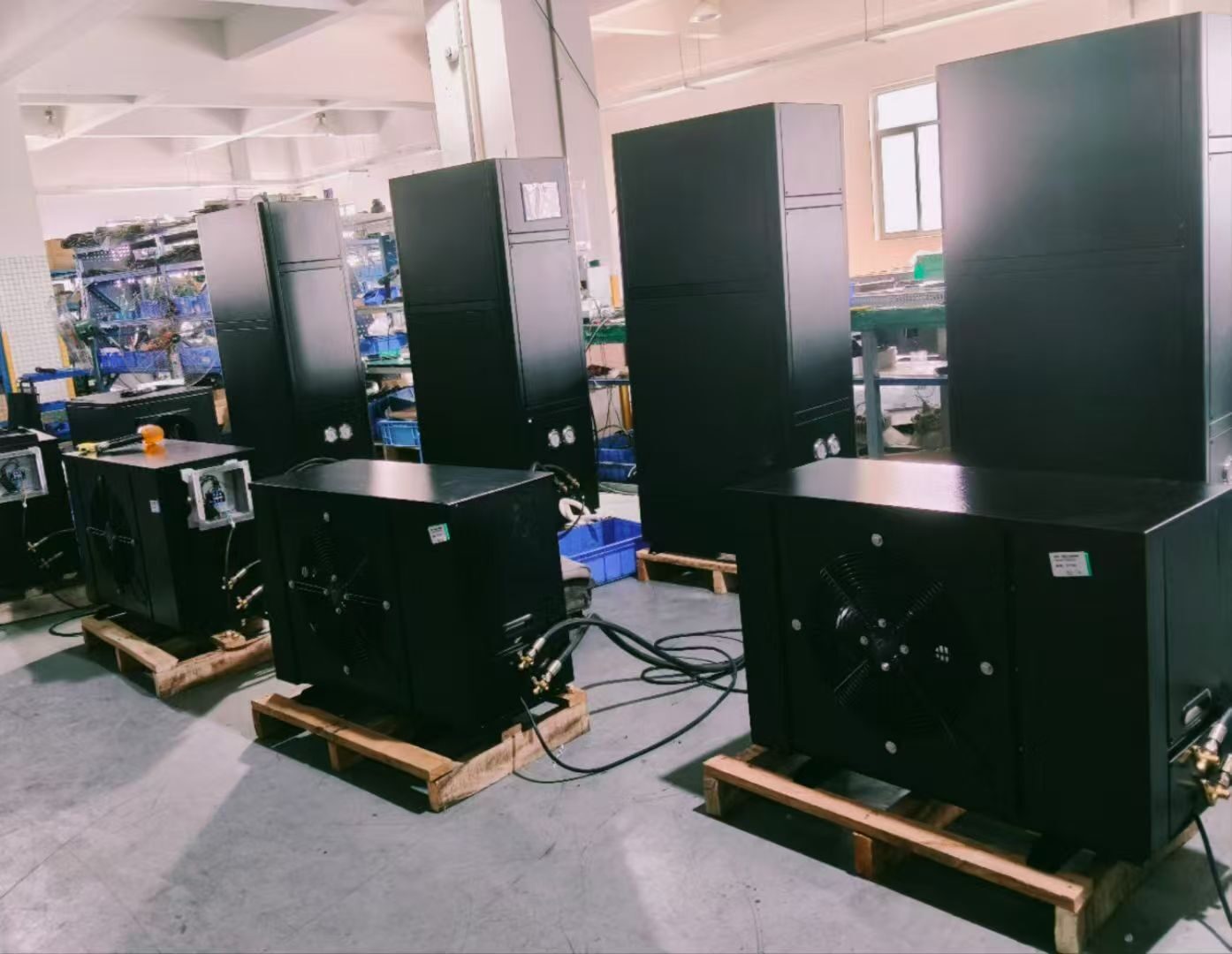
A server room cooling load calculation should begin with power, not floor area. Almost all electrical power consumed by servers, storage, switches, and other IT equipment becomes heat. Measured real power is therefore the preferred starting point for estimating the room’s sensible cooling load.
A server room cooling load calculation is an energy-balance method that converts in-room electrical and building loads into the required sensible cooling capacity and airflow. The planning equation is:
Getting a credible answer still requires more than adding watts. Define the calculation boundary, avoid double counting, separate sensible from total capacity, calculate airflow, and treat future growth and redundancy as different design decisions.
This guide provides a copyable worksheet and a worked 20 kW IT-room example, matched with real product paths from SongXin HVAC’s precision cooling systems range. Use it for early planning, budget preparation, and supplier discussions — it is not a final HVAC design, code-compliance analysis, equipment performance assurance, or substitute for commissioning by qualified professionals.
Start with power, keep scenarios separate, select on net sensible capacity
- Start with measured real IT power and a written room boundary; floor area alone does not describe the equipment heat.
- Add UPS, PDU, lighting, people, envelope, and outdoor-air loads only when their heat is released inside that boundary.
- Keep the current, documented future, and theoretical maximum scenarios separate so an unexplained margin does not hide uncertainty.
- Select by net sensible capacity and airflow at project conditions. Nominal tons and total capacity are not enough.
- Add growth before redundancy, then prove N+1 operation by removing one unit during a controlled commissioning test.
Server room cooling load calculation: the short answer
For IT equipment located entirely inside the cooled room:
A measured 20 kW IT load therefore creates approximately 20 kW of local sensible heat before UPS and distribution losses, lighting, people, the envelope, ventilation, humidification, and other room loads are added.
Use these exact conversions from the NIST Guide to the SI:
- 1 W = 3.4121416 Btu/h
- 1 refrigeration ton = 12,000 Btu/h
- 1 refrigeration ton = 3.516853 kW
Two separate acceptance questions govern the selection:
- Heat-removal capacity: The available net sensible capacity must equal or exceed the design load at the actual indoor and outdoor conditions.
- Air-delivery capacity: The selected airflow and air path must serve every rack without excessive bypass or recirculation.
Define the server room cooling calculation boundary first
Draw a boundary around the space being cooled. Mark every heat source as inside or outside it. Typical inside-boundary items include servers, storage, switches, and routers; rack-mounted PDUs and floor-mounted distribution equipment; UPS equipment and batteries when installed in the room; lighting, displays, and monitoring devices; occupants during maintenance; and exterior walls, windows, roofs, and unconditioned adjacent spaces.
Do not count the same electrical power twice. Suppose the only meter is at the UPS input — an upstream reading already includes IT load, downstream distribution loss, and UPS loss. Choose one method: bottom-up (add IT power and each electrical loss separately) or top-down (use a metered boundary that already includes downstream loads). Do not combine the two unless the meter scope is documented.
Do not count heat released outside the room. A PoE switch sometimes delivers part of its power to devices in another room. A remote UPS releases its losses at its own location. A split system’s condenser rejects heat outdoors. Only heat released inside the calculation boundary belongs in the room load.
Every heat source must be classified as inside or outside the calculation boundary before adding a single watt.
Verified reference values for the worksheet
| Design input | Verified value and context | Decision affected | Official source |
|---|---|---|---|
| Heat-flow conversion | NIST factor: 2.930711 E-01 W per BtuIT/h | Converts all heat data to a common unit | NIST |
| Refrigeration ton | 12,000 BtuIT/h = 3.516853 E+03 W | Converts the final duty load; does not select a product | NIST |
| Recommended A1–A4 equipment-inlet temperature | 18–27°C | Establishes a recommended operating envelope, subject to the most restrictive equipment | ASHRAE Handbook, Ch. 20 |
| A1–A4 moisture guidance | −9°C to 15°C dew point; upper RH depends on verified corrosion conditions | Prevents a legacy fixed-RH band from replacing current guidance | ASHRAE Handbook, Ch. 20 |
| Air sensible-heat relationship | Q(kW) = 1.21 × airflow(m³/h) × ΔT(°C) ÷ 3600 | Checks airflow needed to transport the calculated sensible heat | Uptime Institute |
ASHRAE’s recommended envelope is not a universal thermostat setpoint. The room target must satisfy the most restrictive equipment — corrosion conditions, batteries, tape systems, and high-density equipment narrow the acceptable range when their specified limits are tighter.
Standards that frame — but do not replace — the sizing calculation
Two management-system standards help an owner govern a critical IT room, but neither supplies a cooling setpoint or equipment capacity. ISO 50001 supports a systematic energy-management process — use metered power, defined baselines, and operating trends to evaluate efficiency after thermal compliance is proven. ISO/IEC 27001, commonly shortened to ISO 27001, supports information-security management, including governance of remote monitoring and control access.
These standards support management decisions. ASHRAE equipment guidance, the room load, manufacturer performance data, local codes, and commissioned measurements still determine the technical selection.
Copyable server room cooling load worksheet
Use one column for the current measured condition and another for the documented future configuration.
| Load category | Preferred data source | Current (kW) | Planned (kW) | Calculation rule |
|---|---|---|---|---|
| IT equipment | Rack PDU, branch, or UPS output meter | 20.000 | 23.000 | Actual real input power |
| PDU/distribution loss | Input-output difference or efficiency curve | 0.408 | 0.469 | Pout × (1/η − 1) |
| UPS loss | Efficiency curve at planned load | 1.074 | 1.235 | Pout × (1/η − 1) |
| Battery charging | UPS manufacturer data | 0.000 | 0.000 | Add only for the defined recovery case |
| Lighting | Connected fixture wattage | 0.250 | 0.250 | Installed watts |
| People | Peak simultaneous occupants | 0.200 | 0.200 | Project-specific sensible heat |
| Envelope and solar | HVAC load calculation | 1.000 | 1.000 | Walls + roof + windows + solar |
| Ventilation/infiltration | HVAC load calculation | 0.000 | 0.000 | Sensible + latent load |
| Other internal loads | Monitoring, controls, security, displays | 0.000 | 0.000 | Measured or manufacturer data |
| Total duty load | 22.932 | 26.154 | Sum of included loads | |
| Documented future additions | Approved rack and equipment schedule | 0.000 | 3.000 | Add explicit planned load |
| Final duty cooling load | 22.932 | 26.154 | Current or planned total | |
| Redundant capacity | Availability requirement | 22.932 | 26.154 | Add after duty load is known |
Record the date, workload, meter location, equipment configuration, and source beside every major input. A value without a boundary or source is difficult to audit later.
Five steps to a credible cooling load
Measure or estimate the IT equipment load
Use real power in watts or kilowatts, not apparent power in kVA. Prefer data in this order: metered real power from rack PDUs, branch circuits, or UPS output; a manufacturer configuration-specific power tool; published typical and maximum input or heat data for the exact configuration; and nameplate ratings as a clearly labeled upper-bound case.
For a new room, keep at least three distinct cases: current measured or opening-day load, documented planned deployment, and theoretical nameplate maximum. Do not hide these different risks inside an unexplained generic margin.
Add UPS and distribution losses
Electrical conversion losses become heat where the equipment is installed. When efficiency at the selected load is known:
For example, a UPS delivering 20 kW at 95% efficiency has an input of 20 ÷ 0.95 = 21.053 kW, giving a UPS heat loss of 21.053 − 20 = 1.053 kW. Use the current manufacturer efficiency curve at the expected load — rated peak efficiency does not automatically apply at low load. See the DOE 2024 data-center design guide.
Add lighting, people, and other internal loads
Use connected lighting wattage where possible. Schneider Electric White Paper 25 uses 1.33 W/ft² (14.32 W/m²) for lighting and 100 W per person for occupancy when detailed values are unavailable — these are estimating inputs, not universal code values.
Server rooms are usually lightly occupied, but technicians sometimes stay during maintenance, recovery, or commissioning. List displays, KVM equipment, monitoring gateways, and security devices instead of burying them in an opaque allowance.
Calculate envelope, outdoor-air, and moisture loads
A room surrounded by conditioned interior spaces has a low envelope load when adjacent conditions are stable. A room below a roof or beside an exterior wall, window, loading area, or unconditioned space has a different envelope load. The project HVAC load calculation must quantify wall/roof/floor/glazing heat transfer, solar gain, infiltration and ventilation, sensible and latent components, humidification or dehumidification demand, and altitude-related air-density effects.
Floor area alone cannot determine server room cooling. Area affects lighting and envelope load, but it does not describe concentrated 24/7 IT heat.
Keep growth separate from redundancy
Growth asks: how much additional IT load is documented during the design period? Redundancy asks: how much cooling must remain available when equipment is unavailable? They are not the same capacity. Build growth from a rack and power plan. Add redundant capacity only after the future duty load is established.
Worked server room cooling load calculation: a 20 kW IT room
Source: author-created worked example using cited NIST conversion constants and the following explicit project assumptions. It is not a product recommendation or measured site result.
Assumptions: IT equipment 20.000 kW · PDU efficiency at design load 98% · UPS efficiency at design load 95% · Lighting 0.250 kW · Two occupants 0.200 kW total · Envelope and ventilation load from the project HVAC calculation 1.000 kW. The UPS and PDU are inside the cooled room.
PDU loss:
UPS loss (without double counting — the UPS supplies the PDU input, not only the server output):
Totals: IT equipment 20.000 kW + PDU loss 0.408 kW + UPS loss 1.074 kW + Lighting 0.250 kW + People 0.200 kW + Envelope/ventilation 1.000 kW = Total duty load 22.932 kW
The duty estimate is therefore 22.93 kW, 78,248 Btu/h, or 6.52 refrigeration tons before redundant capacity is added. This is a unit conversion — not a completed equipment selection.
Buyer decision: use 22.932 kW as the minimum example duty for capacity comparison. Select a product only after its project-condition net sensible output is no less than that value; otherwise reject it as undersized.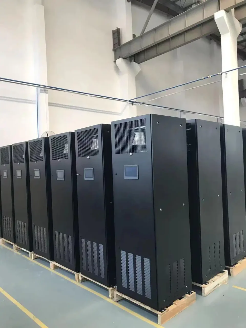
Capacity alone cannot predict rack inlet temperature — airflow and air path must be reconciled together.
Calculate the server room airflow requirement
Capacity and airflow are connected by air temperature rise. Use the Uptime Institute sensible-heat relationship:
For the 22.932 kW example at an author-selected 10°C design air-temperature rise:
The 10°C value is an example, not a universal server-room standard. The DOE guide reports a server temperature-rise range from 10°F to more than 40°F as equipment and load change. Use measured rack data, IT manufacturer airflow, or a coordinated design assumption.
If the cooling system delivers too little air, racks draw hot exhaust back into their inlets — this recirculation raises local inlet temperature. Excess air without effective distribution creates bypass and unnecessary fan energy.
Reconcile these five items before selection
| Check | Required evidence |
|---|---|
| Room sensible load | Documented current and planned kW |
| Cooling-unit capacity | Net sensible capacity at project indoor/outdoor conditions |
| IT airflow demand | Manufacturer data or measured rack airflow/ΔT |
| Cooling-unit airflow | Performance at the selected fan setting |
| Air path | Rack layout, containment, supply, and return arrangement |
Add N+1 cooling redundancy correctly
Let Qd be the duty design load and Cu be one unit’s net sensible capacity at the design condition.
For N+1, add one unit beyond the number needed for duty. Verify:
For the 22.932 kW example, two arrangements illustrate the logic:
| Arrangement | Required capacity per unit | Behavior with one unit unavailable |
|---|---|---|
| One duty unit plus one standby | ≥ 22.932 kW net sensible each | The other unit carries the full duty load alone |
| Two duty units plus one standby | ≥ 11.466 kW net sensible each | Two remaining units still supply at least 22.932 kW combined |
The modular option has its own part-load behavior and airflow increments. It also changes footprint, power feeds, condensate paths, and lifecycle cost. Test the actual sequence — N+1 equipment count alone does not establish an Uptime Institute Tier; topology and distribution paths also matter.
Select by net sensible capacity, not nominal tons
Server rooms are dominated by sensible heat. Comfort-cooling products are frequently advertised by total capacity, including latent performance. For every candidate unit, request gross and net sensible capacity, gross total capacity and sensible heat ratio, fan heat treatment in the published value, entering dry-bulb and wet-bulb conditions, outdoor design condition and altitude correction, minimum and maximum cooling output, airflow at the selected fan setting, low-ambient operating range, and restart/control behavior after power restoration.
Use net sensible capacity at project conditions in the redundancy calculation. Catalogue tonnage alone is insufficient.
For room-level equipment options, compare the result with computer room air-conditioning equipment and the broader precision cooling systems range. Evaluate a closer-coupled in-row cooling system when individual racks have much higher density than the room average.
Net sensible capacity at project conditions — not the model name — determines whether a unit passes the redundancy test.
Match room profile to cooling category
Computer Room Air Conditioner
Room-level cooling for computer rooms, network rooms, and telecom spaces with uniform rack density.
View CRAC Systems →
In-Row Cooling
Targeted rack-row cooling for high-density areas where room-average capacity cannot predict local inlet temperature.
View In-Row Cooling →
Data Center Cooling Solutions
Facility-level planning for data centers where cooling reliability is directly linked to uptime.
View Data Center Solutions →Common server room cooling calculation errors
Using room area as the main load
A small room sometimes contains a large IT load. Area affects envelope and lighting, not the equipment power inventory.Treating kVA as kW
Cooling calculations require real power. Convert kVA only when the applicable power factor and operating condition are known.Adding metered power twice
Do not add IT, PDU, and UPS heat again when the selected meter already includes them.Sizing from an idle reading
Use a documented high-load case and the planned deployment schedule, not a convenient low reading.Applying an arbitrary growth %
List planned racks and equipment explicitly. Keep an uncertain allowance visible and justified.Multiplying IT heat by PUE
PUE is a facility energy ratio. It is not a general multiplier for a single room’s cooling load.Selecting nominal total capacity
The room needs net sensible capacity at its actual conditions — a nominal model designation overstates usable output.Ignoring airflow and distribution
Capacity alone cannot predict rack inlet temperature. Recirculation and bypass must be checked in the installed arrangement.Counting redundancy as growth
A module needed for future duty cannot also be counted as standby capacity at that future load.Commissioning and acceptance checks
The installed system must prove the calculation. A practical sequence: reconcile installed racks, IT devices, UPS, and distribution equipment with the worksheet; record real power under a representative high workload; record each cooling unit’s supply/return temperatures, airflow, and control state; measure rack inlet temperature at the top, middle, and bottom; inspect blanking panels, cable openings, containment, bypass, and recirculation.
Then demonstrate duty/standby rotation and part-load control; simulate loss of one cooling unit under a controlled safe test plan; demonstrate that remaining capacity and airflow maintain the specified inlet limit; test temperature, humidity, condensate, fan, compressor, filter, power, and communication alarms; record the automatic restart sequence after a power interruption; and save readings, sensor locations, setpoints, and software settings as the operating baseline.
ENERGY STAR recommends checking server inlet temperatures at the center of the top, middle, and bottom of racks near the equipment front. A single wall thermostat cannot reveal every hotspot.
A reconciled bill of quantities and commissioning checklist ties the worksheet to what is actually installed.
Server room cooling selection flow
Follow this sequence so capacity, airflow, and one-unit-out performance are all resolved before award.
Server room cooling specification checklist for an RFQ
Provide every bidder with the same inputs: present and planned IT load in kW plus the measurement source and date; rack count, per-rack load, and the most densely loaded rack; UPS and PDU locations and efficiency curves; room dimensions, rack layout, and exterior exposure; equipment-inlet temperature and moisture requirements; outdoor design conditions and altitude; calculated sensible and latent loads; required IT airflow or coordinated ΔT; redundancy objective and safe degraded condition; available electrical supplies, heat-rejection path, and condensate route; monitoring, alarm, integration, and restart requirements; and expansion plan and commissioning acceptance criteria.
Ask each supplier to return net sensible capacity and airflow at the same project conditions. Otherwise, nominally similar offers use different rating assumptions and are not technically comparable. For a project-specific configuration discussion, see SongXin’s precision cooling systems range and documentation & certifications support.
Server room cooling load calculation FAQ
Does 1 kW of IT power require 1 kW of cooling?
Approximately 1 kW of local sensible heat must be removed for every 1 kW consumed by IT equipment inside the room boundary. The total requirement is higher after adding the in-boundary electrical, lighting, occupancy, envelope, ventilation, and other loads.
Should I use actual or maximum server power?
Use measured real power for the present case and configuration-specific planned power for the future case. Keep a nameplate maximum as a separate upper-bound check. This prevents an electrical provisioning limit from becoming the expected thermal load.
How much safety margin should I add?
No single percentage fits every room. Derive future capacity from the documented rack and power plan. Document an uncertainty allowance separately, then calculate standby capacity from the required one-unit-out condition. This keeps planned duty, design uncertainty, equipment derating, and redundancy visible instead of hiding four decisions inside one margin.
What temperature should a server room maintain?
ASHRAE’s recommended A1–A4 equipment-inlet range is 18–27°C. Set the operating target inside that envelope and inside the limits of the most restrictive installed equipment, using the applicable dew-point, relative-humidity, and corrosion conditions rather than a legacy thermostat and RH band.
Is a 6.5-ton unit suitable for the 20 kW example?
Not necessarily. The 6.52 tons is an author-created conversion of the 22.932 kW example using the NIST constants. It is not a model selection. The unit must deliver at least the required net sensible capacity and airflow at project conditions, then pass the one-unit-out redundancy test.
Does N+1 mean buying two identical units?
Only when one unit carries the entire design duty after the other becomes unavailable. Larger loads use several duty modules plus one additional module where the modular architecture is suitable. Size the arrangement with net sensible capacity at project conditions, then test airflow, controls, power feeds, condensate paths, alarms, and transfer sequence under the defined degraded condition.
When is this worksheet not enough?
Detailed engineering is necessary for major exterior loads, high altitude, high-density racks, or persistent hotspots. It is also necessary for shared central systems, liquid cooling, strict availability requirements, and complex air paths. Use site measurements or CFD when room-average capacity cannot predict local rack conditions, but retain field commissioning as the acceptance test.
Prove capacity and airflow before you buy
Start with measured real power and a clear room boundary. Add each in-room loss once. Keep present and future scenarios separate, and convert the duty load only after the inputs are traceable. Then prove net sensible capacity and airflow at the project conditions. Add redundancy as a separate layer and demonstrate it with a one-unit-out test at the rack inlets.
References
- ASHRAE Handbook—Data Centers and Telecommunication Facilities
- NIST Guide to the SI—Heat Flow Rate Conversions
- Schneider Electric—Calculating Total Cooling Requirements for Data Centers
- U.S. Department of Energy—Data Center Design Guide
- Uptime Institute—Data Center Cooling Guidance
- Uptime Institute—Tier Classification Myths and Misconceptions
- ENERGY STAR—Raise the Temperature