Modular AHU Replacement: Access, Assembly and Handover
Technical guide · September 30, 2026
An air handling unit can fit the plant-room footprint and still be impossible to deliver, assemble or maintain. An AHU retrofit in an existing building must account for every stage between the delivery vehicle and the unit’s eventual component replacement.
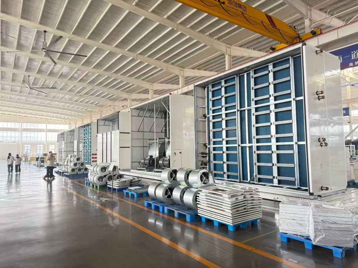
Sectional and knock-down AHUs can address restricted access, but each needs a different level of site assembly and verification. The word “modular” alone does not establish what will pass through a doorway. Functional sections, approved shipping sections and components permitted for site disassembly are different things. The replacement plan needs the manufacturer’s actual transport and assembly information before the order is released.
SongXin’s modular air handling unit range describes configurable air-treatment sections. For a retrofit, request confirmation of the proposed delivery arrangement separately from the functional configuration. The workflow below shows how to connect that proposal to a surveyed building and a practical handover plan.
Key takeaways
- “Modular” does not guarantee access. Check packaged shipping dimensions, including handling equipment, against every door, turn and lift.
- Plan three separate spaces: the transport route, assembly workspace and permanent service clearance, including coil withdrawal.
- Rebuild the fan pressure budget for new filters, coils and heat recovery. In the example, 900 versus 1,200 Pa changes fan input from 4.17 to 5.56 kW.
- Verify the site-assembled casing, filter paths and drainage under the agreed test scope. Factory data does not establish workmanship at site joints.
About the examples in this guide: All numbers in the worked examples are fictional assumptions chosen to demonstrate the method. They are not typical values, design allowances, or measured SongXin performance. Use the selected equipment’s data and your project conditions for any real decision. In formulas, x means multiplication and ~= means approximately equal.
Don’t Size the Replacement AHU from the Old Nameplate
Start with the current requirement and the existing system’s condition. Record the served areas, required airflow, operating hours, filtration duty, cooling and heating loads, available utilities and agreed indoor conditions. Identify changes in occupancy, room use or operating schedule since the original installation.
Measure the existing installation where those measurements can inform the replacement. Useful records include airflow, fan setting, pressure across significant components, water temperatures and flows, filter condition and current control behavior. Note the conditions under which measurements were taken. A reading during partial occupancy should not silently become the new design duty.
Separate three findings in the survey:
- Requirements the new unit must meet, such as the agreed airflow and coil duty.
- Existing limitations that the project must accommodate or correct, such as restricted access or inadequate branch pressure.
- Suspected faults that still need investigation, such as a low airflow caused by a blocked filter rather than an undersized fan.
This prevents the project from reproducing a problem merely because it was part of the previous installation. SongXin’s retrofit and upgrade support is a relevant starting point for discussing the existing conditions and proposed scope.
Will the New AHU Fit? Transport, Assembly and Service Space
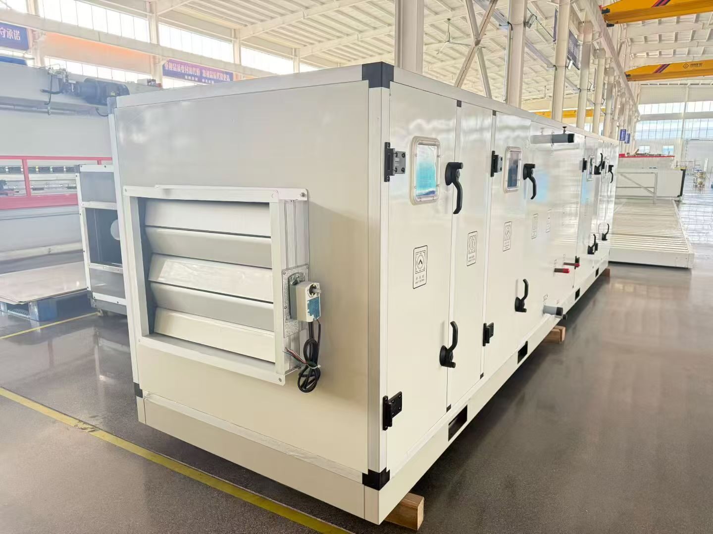
The route constraint should influence the proposed construction early. Ask the manufacturer to identify which of these arrangements it is actually offering:
REFERENCE TABLE · Scroll horizontally on smaller screens to read all columns.
| Proposed arrangement | What it can solve | What still needs verification |
|---|---|---|
| Sectional AHU: factory-built sections joined on site | Reduces shipping length where the individual cross-section fits the route | Largest section dimensions, coil/fan projections, mass, joining access and assembled performance |
| Knock-down AHU: manufacturer-approved site assembly from smaller components | May overcome a restrictive opening that complete sections cannot pass | Permitted disassembly, trained assembly responsibility, casing continuity, test scope and warranty conditions |
| Several smaller AHUs or fan/coil modules | May permit different routes or phased installation | Space for duplicated connections and maintenance, airflow distribution, controls and performance when one unit is unavailable |
Do not describe the third option as redundant simply because it has two units. Two units each carrying half the required duty leave only half the capacity if one is unavailable. Any standby requirement must be demonstrated against the load that must remain served.
Use one coordinated drawing set to show transport, assembly and permanent service space. Each answers a different question.
REFERENCE TABLE · Scroll horizontally on smaller screens to read all columns.
| Space requirement | What must be shown | Typical reason a footprint-only check misses it |
|---|---|---|
| Transport route | The largest approved shipping sections, their orientation, packaging and handling equipment throughout the route | A cabinet dimension omits a crate, lifting projection, skid or turning restriction |
| Assembly workspace | Positioning sequence, access to section joints, tools, temporary supports and material staging | The final arrangement fits, but the last joint cannot be reached or tightened |
| Permanent service space | Door movement, filter withdrawal, coil and fan removal, controls access and replacement-component route | A person can stand beside the unit, but a coil cannot be withdrawn |
Measure clear openings rather than relying on nominal door sizes. Include door hardware, thresholds, overhead services, changes in level and the corners on either side of the opening. A section that passes through a straight doorway may still fail the turn immediately beyond it.
The route survey should extend to loading areas, lifts, stairs or temporary openings where relevant. Record individual section masses and the proposed handling arrangement so the responsible specialists can assess lifting, floor loading and structural constraints. A manufacturer’s shipping weight is an input to that assessment, not evidence that the building can support the move.
This air-handler installation manual illustrates why this coordination matters: it calls for site support, service access, coil-removal space and sufficient height for the condensate arrangement, with unit-specific information taken from the submittals. Its dimensions apply to that equipment; use the selected manufacturer’s approved details for the project.
Example: The Casing Fits the Door, the Shipping Crate Doesn’t
In this fictional access example, the dimensions are:
- Surveyed clear doorway width: 1,050 mm.
- Quoted AHU section casing width: 980 mm.
- Approved packaged shipping width: 1,120 mm.
Comparing only the casing with the doorway suggests 70 mm of spare width. Comparing the shipping package with the same opening shows a 70 mm shortfall instead:
Apparent casing clearance = 1,050 - 980 = 70 mm
Shipping-width shortfall = 1,120 - 1,050 = 70 mm
Neither calculation resolves handling clearance, height or turning space. The result is a request for a revised delivery plan, not permission to remove packaging or dismantle the section. Obtain manufacturer confirmation of any permitted unpacking or disassembly, the resulting dimensions, component protection and reassembly responsibility.
Possible resolutions include smaller approved shipping sections, a revised route or an authorized temporary opening. Assess the cost, structural implications, weather protection and reinstatement work before committing to an option. If none is practical, the selected construction may be unsuitable for the building even though its operating performance is acceptable.
Make the service check just as explicit. In the service-space example, a 1,000 mm clear aisle beside a coil that needs 1,400 mm of withdrawal space leaves a 400 mm deficit. An access door that opens freely does not resolve that deficit. Revise the arrangement or obtain a manufacturer-approved component removal method before the aisle is enclosed by permanent services.
When documenting the route, retain the limiting measurement for each segment together with a photograph or surveyed drawing. Record the moving envelope including the approved skate, trolley or lifting arrangement. Check the transition into the opening, not just the opening itself. The calculation for a straight doorway does not establish the turning envelope of a long coil section.
For an occupied building, also record when each part of the route is available and what must be reinstated. A corridor accessible overnight but needed as a building route during the day creates a delivery and staging constraint even if its dimensions are adequate. Include any temporary opening and reinstatement work in the priced scope.
Recalculate Fan Pressure and Power for the New AHU
Matching the old airflow and external static pressure is insufficient when the internal filters, coils, heat recovery or silencers change. The fan must overcome the relevant internal and external losses at the required airflow. Keep the pressure definitions consistent with the supplier’s selection, including any velocity-pressure treatment.
In this fictional fan-duty example, use 10,000 m³/hour and the following total-pressure budget:
REFERENCE TABLE · Scroll horizontally on smaller screens to read all columns.
| Contribution at the selected duty | Assumed pressure requirement |
|---|---|
| Connected external air path | 350 Pa |
| Filters at the declared selection condition | 180 Pa |
| Coil assembly at the declared wet/dry condition | 160 Pa |
| Heat-recovery device | 150 Pa |
| Other internal sections and accounted connection losses | 60 Pa |
| Total fan pressure requirement | 900 Pa |
Specify whether the external requirement already includes inlet and outlet accessories; count each item once. Identify the wet-coil condition and the clean/design/terminal filter conditions in the selection. Confirm the wet-coil and reheat duty before finalizing the air-treatment sections and their pressure losses. The 180 Pa filter value above is only the declared condition for this example, not an end-of-life value.
At an assumed wire-to-air total efficiency of 0.60, the first electrical estimate is:
Airflow = 10,000 / 3,600 = 2.778 m^3/s
Fan input = airflow x total pressure / (1,000 x overall efficiency)
          = 2.778 x 900 / (1,000 x 0.60)
          ~= 4.17 kW
If a more restrictive arrangement requires 1,200 Pa at the same airflow and assumed efficiency, input rises to approximately 5.56 kW. At 4,000 equivalent full-duty hours, the difference is approximately 5,556 kWh/year. This is a constant-duty comparison; a real annual model needs the operating profile and selected efficiency at each point.
The fan performance guide explains the relationship between the fan curve, system curve and operating point. A motor nameplate rating is not the operating electrical input, and a single efficiency value is not valid across every airflow and pressure combination.
This calculation makes the spatial tradeoff visible. A smaller section may solve access while increasing face velocity, component resistance or sound output. A larger section may reduce pressure loss but fail the route or coil-withdrawal check. Compare the offered arrangements at the same duty and service conditions, then decide whether the space saving justifies its operating and maintenance consequences.
Check the fan connections as well as the component schedule. A sharp turn immediately at a fan inlet, an abrupt discharge transition or a nearby obstruction can produce losses that an ordinary straight-duct calculation misses. The discussion of fan system effects explains why the installed connection must be compared with the tested arrangement. In a tight plant room, resolving that geometry can be more useful than selecting a larger motor to compensate for it.
Also check pressure reserve at the agreed loaded-filter condition. If filter loss rises from 180 to an assumed 300 Pa while all other terms remain unchanged, the fan duty becomes 1,020 Pa. Confirm that the selected speed, motor/drive, acoustics and casing pressure limits permit that condition. On a fixed-speed system, greater resistance may instead reduce airflow; available motor power alone does not guarantee the scheduled flow.
Plan Shipping Sections Before Booking the Shutdown
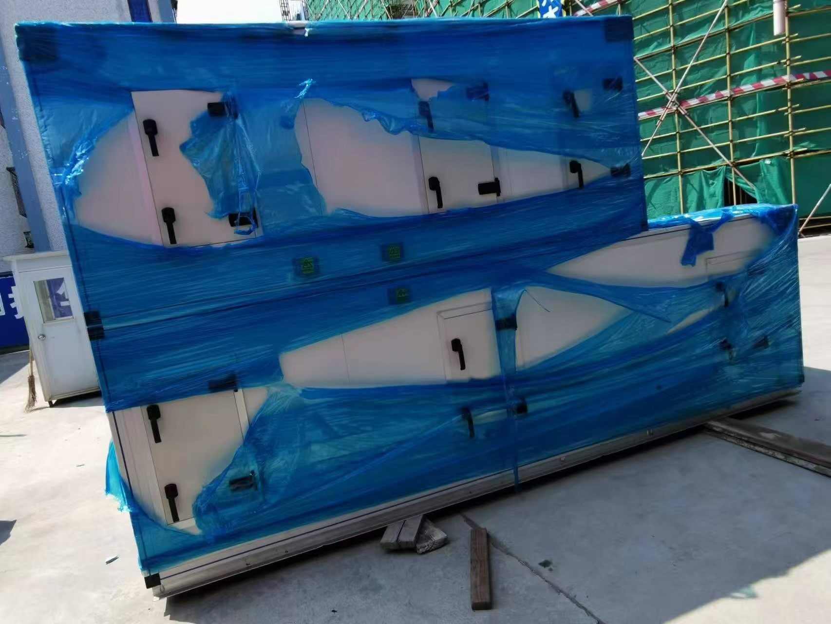
Ask the supplier to issue a section schedule tied to the approved general arrangement. Each shipping section should have an identifier, dimensions including projections, mass, orientation restrictions and the corresponding handling instructions. Mark components or braces that must remain in place, and identify anything the manufacturer expressly permits to be removed.
Then walk the proposed sequence with the installation team and building operator:
- Confirm how the existing unit will be isolated and removed, including its own route and disposal scope.
- Confirm the arrival sequence and protected staging location for every replacement section.
- Check that sections can be placed and joined in the proposed order without trapping access to a later joint.
- Identify the required utility, duct and controls work and the party responsible for each interface.
- Agree the shutdown window, restoration milestones and response if delivery or commissioning is delayed.
Where the served operation needs continuous environmental control, decide the temporary-service requirement with the operator before shutdown. State the spaces, duties and duration that any temporary arrangement must cover. Do not assume that a portable unit or the neighboring system can carry the load without a separate check.
The resulting plan should be specific enough to identify a missing section or inaccessible joint before work begins. A general promise to “assemble on site” leaves too many decisions until the building is already without service.
Site Assembly: Casing Leakage, Filter Bypass and Thermal Bridging
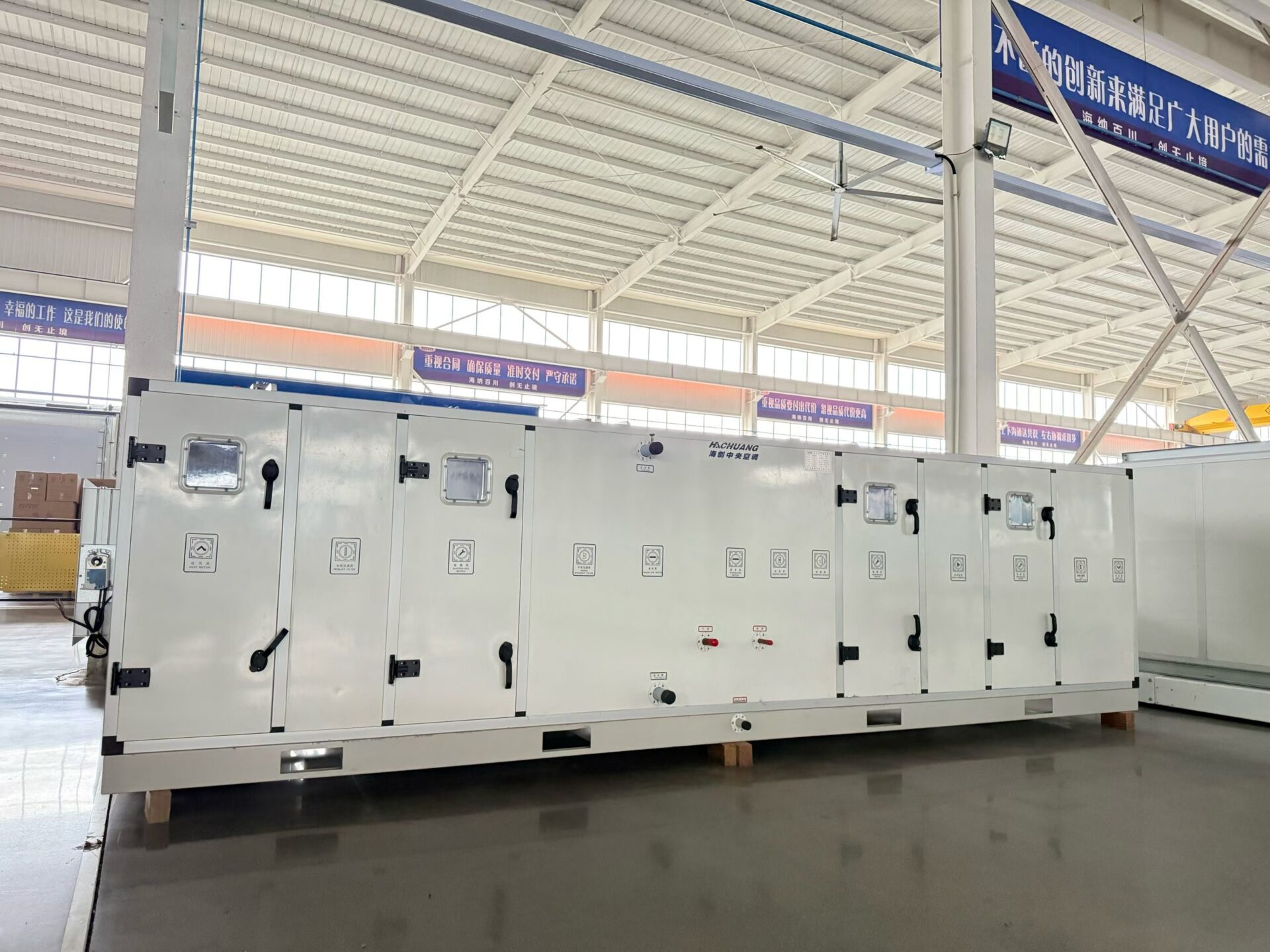
Name who is responsible for the assembled result. The scope should cover the support arrangement, section alignment, joints, internal continuity and the interfaces between mechanical and controls work.
Use the manufacturer’s installation manual and supplied materials for section alignment, joint gasketing and fastening. Record the approved joint detail for the selected unit before assembly.
Before joints become concealed, record their completion and any damage or corrective work. Check that access panels, doors and removable components operate as intended after the unit is assembled. Agree any casing-leakage or filter-bypass acceptance requirement, including its test boundary and method, in the project specification. Factory evidence for a supplied configuration should not be treated as a measurement of workmanship at newly completed site joints.
What Do Leakage, Bypass and Thermal-Bridge Checks Prove?
These are separate failure mechanisms. The Eurovent 6/18 quality recommendation discusses casing leakage, filter bypass and thermal performance separately. Its 2022 edition provides a useful framework; the purchase specification should identify the applicable test standards and editions for the actual project.
- Casing leakage: air crosses the unit envelope. Leakage into a negative-pressure section can introduce untreated air; leakage out of a positive-pressure section can reduce delivered airflow. Record the test section, pressure sign and magnitude, sealed openings and leakage result. A class name without its tested construction and conditions is incomplete evidence.
- Filter bypass: air passes around the media or frame. A higher-efficiency filter cannot correct an unsealed path around it. Inspect and test the installed filter/frame arrangement under the specified method, including site-assembled joints that affect that path.
- Thermal bridging and vapor-seal discontinuity: local cold surfaces or moisture paths can remain even when nominal panel insulation is adequate. Section joints, doors, frames and pipe penetrations deserve particular attention after site assembly.
In this fictional filter-bypass example, assume media captures 80% of a specified particle challenge while 3% of the total air bypasses it without capture. Overall removal is only (1 − 0.03) × 0.80 = 77.6%. This mixing result explains why media efficiency differs from installed removal; determine the required classification and acceptance method separately.
In this fictional condensation example, air at 30°C and 18 g/kg has a dew point near 23.2°C at sea-level pressure. A local exterior surface at 21°C is below that dew point and is vulnerable to condensation. The humidity relationship is described in ASHRAE’s psychrometrics guidance. A retrofit inspection should therefore check local cold bridges and sealed penetrations under representative conditions, rather than relying only on the stated panel thickness.
For outdoor arrangements, include the manufacturer’s weather-sealing details and the transition to the building roof or supporting construction. Assign responsibility for both sides of that interface so a later leak does not fall between two scopes.
Duct, Drain Trap, Power and Controls Interfaces
Ductwork and pressure. Confirm the connection geometry, available external pressure and access to dampers and measuring points. A revised filter or attenuator arrangement can change the fan duty. Reconcile those changes with the final selection before commissioning.
Water and drainage. Confirm coil connections, required flow, available branch pressure, valve access and the condensate route. Allow for the selected drain-trap arrangement and the pressure at the drain location. Set the support height accordingly; a convenient low plinth is not useful if the drain cannot operate as designed. Use the manufacturer’s dimensions rather than a generic trap rule.
Pressure can make a geometrically convenient drain ineffective. In a draw-through arrangement, negative pressure at the pan can pull air through the drain and interfere with drainage. The relevant pressure is the local pan pressure at the worst specified operating condition, including the agreed filter-loading condition—not simply the AHU’s external static pressure.
In this fictional drainage example, a pressure difference of 750 Pa is equivalent to approximately 76.5 mm of water column:
Equivalent water height = pressure / (water density x gravity)
                        = 750 / (1,000 x 9.81)
                        = 0.0765 m
That is a pressure conversion, not a complete trap dimension. Seal geometry, operating margin, drain diameter, cleaning access and downstream fall still matter. The manufacturer’s installation manual cited above distinguishes negative and positive sections and includes loaded-filter pressure in its sizing instructions. Obtain the selected unit’s approved detail before setting the drain-pan elevation. A fan-off pour test alone does not establish drainage while the fan is running.
Power and controls. Coordinate the actual electrical supply, motor or drive arrangement, sensor locations, control-panel access and the building-management interface. Define the required operating commands, status feedback, alarms and protective interlocks in a point schedule and functional description. Existing cables or point names do not prove compatibility with the new package.
Maintenance. Show the physical withdrawal paths for filters, fans and coils on the final drawing. Keep those paths clear of permanent pipes, cable trays and other equipment. Include a practical route for bringing a future replacement component back into the building.
These checks belong to the final installed arrangement. Completing them against an early drawing is insufficient if the section order, access side or utility routing later changes.
AHU Commissioning and Handover Checklist
Agree the acceptance evidence before installation so the project has the necessary measuring points and responsibilities. A useful handover package connects what was ordered, what was assembled and what was tested.
REFERENCE TABLE · Scroll horizontally on smaller screens to read all columns.
| Handover item | Evidence to retain |
|---|---|
| Delivered configuration | Section identifiers, final component schedule, damage records and approved substitutions |
| Installed arrangement | As-built drawing showing access sides, service clearances, supports and connected utilities |
| Assembly quality | Completed joint records, remedial-work records and results of any specified leakage or bypass tests |
| Air and water performance | Measured airflow, pressure and water-side data with fan settings, valve positions and test conditions |
| Environmental duty | Cooling, heating or humidity results at the available test conditions, with any remaining seasonal verification identified |
| Control behavior | Recorded responses for the agreed modes, alarms and interlocks |
| Maintenance readiness | Access demonstration, filter and spare-part identification, operating instructions and staff handover |
A commissioning test on a mild day may establish airflow and controls without establishing peak cooling duty. Record that boundary and schedule the remaining verification under the contract, rather than labeling an untested condition as passed.
Sequence acceptance so that one apparent success does not conceal a failure elsewhere:
- Before operation: reconcile the delivered sections and final drawings; close access, supports, joint work, pipe tests and electrical/control checks under the responsible trades’ procedures.
- At the agreed airflow: record fan speed, power, pressure losses and balancing results together. If power is lower because airflow is below duty, the result does not demonstrate an efficiency improvement.
- During cooling and condensate production: record entering/leaving air and water conditions, verify the drain under operating pressure, and inspect relevant casing surfaces and penetrations for moisture.
- During functional tests: verify commanded modes, actuator responses, alarm visibility, protective functions and restart behavior under the agreed test plan. A BMS command changing on screen does not prove the field device responded.
- At maintenance handover: demonstrate access to filters, valves, drives and drains, and confirm the documented route for later fan or coil replacement.
Use the existing-unit survey as a comparison only when the duties and measurement boundaries match. If the new unit serves more outdoor air, different filtration or a changed occupancy, its absolute kW cannot be compared directly with the old reading as proof of an energy saving. Normalize the comparison or report the changed service explicitly.
The replacement is ready for handover when the evidence shows a serviceable installation that performs its agreed duty, and any outstanding work has a named owner and completion arrangement. The unit’s successful arrival in the plant room is only one stage of that process.
Frequently Asked Questions
Can an AHU be dismantled to fit through a door?
Only where the manufacturer approves the disassembly method, resulting transport dimensions and reassembly responsibility. Unapproved dismantling can compromise casing performance and warranty conditions. Obtain the approved route and assembly plan before ordering.
Are two smaller AHUs redundant?
Not automatically. Two units each carrying half the required duty leave only half the capacity if one fails. Demonstrate the remaining capacity against the load that must stay served.
How deep should an AHU drain trap be?
Use the pan pressure at the worst specified operating condition, including loaded filters, and the manufacturer’s approved arrangement. For example, 750 Pa equals about 76.5 mm water column; that conversion alone does not determine the trap depth.
Can the new AHU’s energy use be compared with the old one?
Only when the measurement boundaries and service duties match, including airflow, outdoor-air quantity, filtration and thermal duty. Normalize changed conditions or report them explicitly before claiming an energy saving.
For a SongXin replacement enquiry, send the existing duty, route survey, plant-room drawing, utility information and permitted shutdown window through the project quotation page. Request the proposed shipping sections, assembly method and permanent service requirements with the equipment selection, so access constraints are resolved while the design can still change.