Fresh Air Unit Dehumidification: Size by Supply Dew Point
Technical guide · September 30, 2026
To size a fresh air handling unit for a humid climate, calculate the required supply humidity ratio or dew point from the assigned room moisture load and delivered dry-air flow. Then select the cooling coil and any reheat at that airflow and the required air conditions.
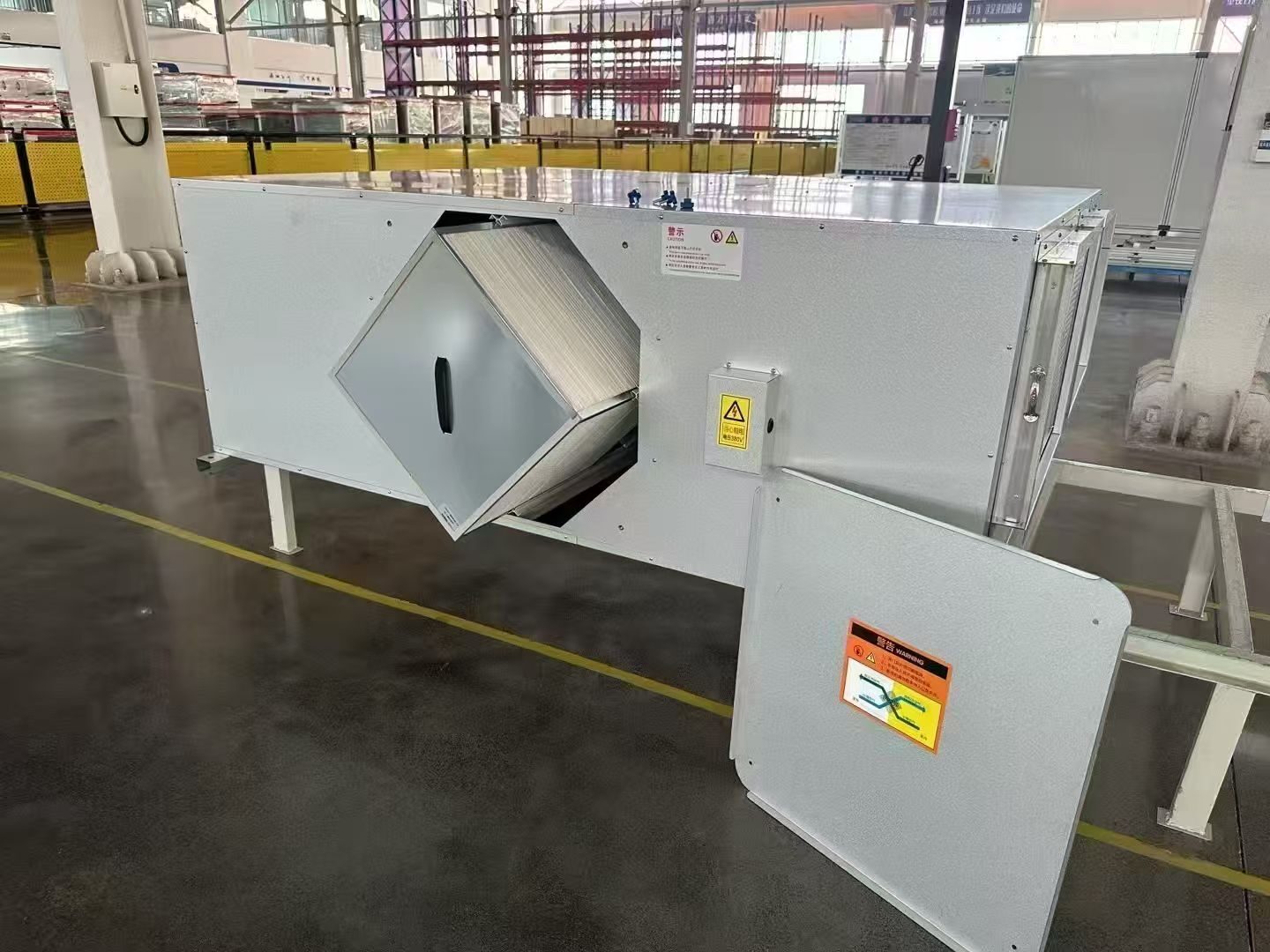
SongXin’s fresh air handling unit range includes application-dependent treatment options. The following method helps define the moisture-control duty before selecting those options. It focuses on cooling and dehumidification of outdoor air; the precise equipment arrangement may use chilled water, refrigerant cooling or other project-specific treatment.
A fresh air handling unit (FAHU) that conditions 100% outdoor air and delivers it separately from room cooling equipment forms a dedicated outdoor air system, or DOAS. In humid climates, specify the required supply-air dryness alongside ventilation airflow.
Key takeaways
- Two FAHUs with identical airflow can provide different humidity control. Specify supply humidity ratio or dew point as well as airflow.
- Reheat lowers relative humidity but removes no water. A low RH reading after reheat does not by itself establish supply-air dryness.
- In the example, holding a room at 10 g/kg against a 3.6 kg/hour moisture load with 1,200 kg/hour of dry air requires 7 g/kg supply air, or about 8.7°C dew point at the stated pressure.
- Useful energy recovery can reduce coil load, but the required supply dryness still follows the room duty. Check the critical zone, not just the building average.
About the examples in this guide: All numbers in the worked examples are fictional assumptions chosen to demonstrate the method. They are not typical values, design allowances, or measured SongXin performance. Use the selected equipment’s data and your project conditions for any real decision. In formulas, x means multiplication and ~= means approximately equal.
FAHU or Fan Coil: Which Equipment Removes Room Moisture?
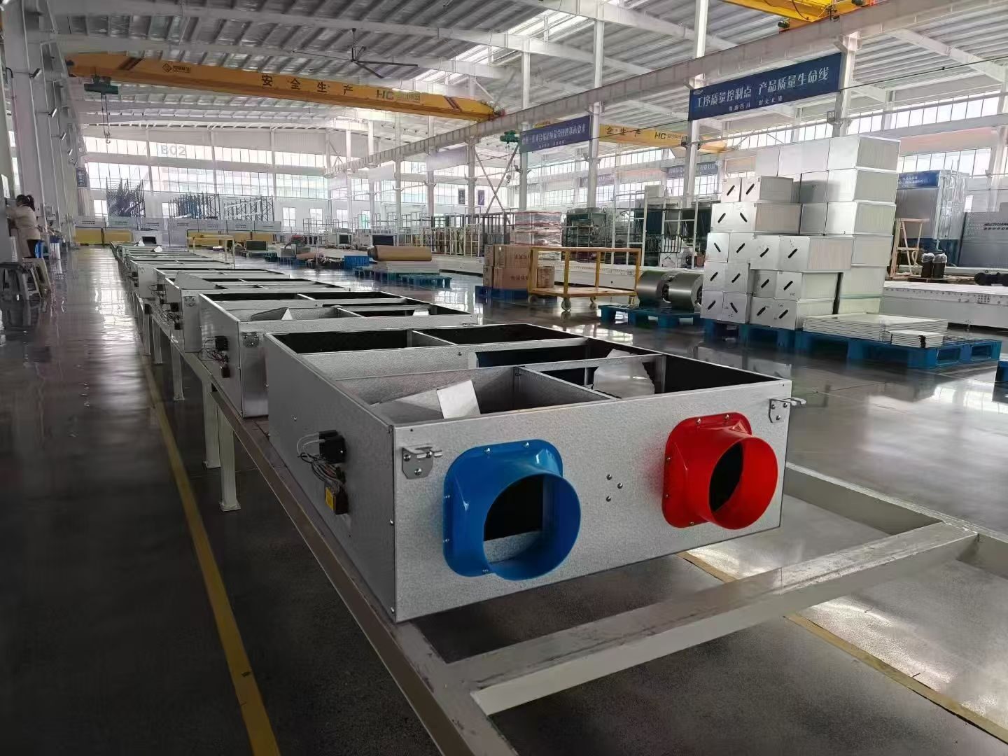
Draw the outdoor-air path through the treatment unit and into the occupied rooms. Add the recirculating room equipment, transfer air, exhaust and likely uncontrolled air entry. Then assign responsibility for two different loads:
- Incoming outdoor-air moisture: the duty associated with conditioning ventilation air before delivery.
- Room moisture: people, activities, infiltration and other moisture sources inside the served space.
A system can be designed to treat only the outdoor-air load, leaving room moisture to terminal cooling units. Alternatively, the fresh air system can supply sufficiently dry air to remove an assigned share of the room load. Either arrangement needs an explicit design basis. A terminal unit intended only for sensible cooling cannot be assumed to remove the remaining moisture.
The dedicated outdoor-air system application guide explains this distinction: incoming outdoor conditions affect equipment dehumidification capacity, while the room latent load determines how dry the conditioned outdoor air must be. That distinction is central to a useful selection schedule.
Why Specify Supply Air Dew Point, Not Relative Humidity
Relative humidity is a temperature-dependent measure. Heating dehumidified air can lower its relative humidity without removing additional water. Consequently, a low relative-humidity reading after a reheat coil does not, by itself, demonstrate increased moisture removal.
Use humidity ratio, expressed as kilograms of water per kilogram of dry air, to calculate moisture flow. Use dew point as a convenient way to specify and monitor the dryness required. Convert between them at the project’s atmospheric pressure using a psychrometric calculation. The room’s comfort requirement still needs its own temperature and humidity limits.
In a cooling-coil arrangement, air is cooled sufficiently to condense moisture. Reheat, if required, then raises its delivery temperature without intentionally adding moisture. These are separate duties: the cooling process establishes dryness, and reheat helps prevent that dry air from overcooling the space. The downstream process is explained in this hot-gas reheat application guidance.
Do not specify a universal supply dew point for every building. The required value depends on the assigned room moisture load and the actual dry-air mass flow delivered to the room.
How to Calculate the Required Supply Air Humidity
In this fictional steady-state example, use the following inputs:
REFERENCE TABLE · Scroll horizontally on smaller screens to read all columns.
| Input | Assumed value |
|---|---|
| Dry-air mass flow delivered by the fresh air system | 1,200 kg of dry air/hour |
| Target room humidity ratio | 0.010 kg water/kg dry air, or 10 g/kg |
| Room moisture load assigned to this system | 3.6 kg water/hour |
| Outdoor-air humidity ratio entering the treatment process | 0.018 kg water/kg dry air, or 18 g/kg |
The assigned room load includes the net effect of relevant moisture sources and uncontrolled air entry for this simplified example. Assume equal dry-air inflow and outflow, no net moisture storage, no moisture addition after treatment, and no other equipment removing the assigned load. The ventilation-air load is not included again in the 3.6 kg/hour room figure.
The steady moisture balance is:
Room moisture removed = dry-air mass flow x (room humidity ratio - supply humidity ratio)

Required supply humidity ratio
= room humidity ratio - (assigned room moisture load / dry-air mass flow)
= 0.010 - (3.6 / 1,200)
= 0.007 kg water/kg dry air
= 7 g/kg
The EnergyPlus Engineering Reference, in its moisture predictor-corrector section, provides the fuller framework, including air exchange, internal sources and moisture storage. Those additional terms matter when the simplified assumptions do not describe the building.
Compare three possible delivered-air conditions under the same example assumptions:
REFERENCE TABLE · Scroll horizontally on smaller screens to read all columns.
| Supply humidity ratio | Moisture carried away from the room | Result against the assigned 3.6 kg/hour load |
|---|---|---|
| 10 g/kg | 1,200 x (0.010 – 0.010) = 0 kg/hour | No capacity to remove the assigned room moisture |
| 9 g/kg | 1,200 x (0.010 – 0.009) = 1.2 kg/hour | A 2.4 kg/hour shortfall |
| 7 g/kg | 1,200 x (0.010 – 0.007) = 3.6 kg/hour | Balances the assumed room moisture load |
All three cases can have the same ventilation airflow. Their ability to control room humidity is different.
The treatment equipment’s moisture-removal duty is larger than the room figure because it must first handle the incoming outdoor air:
Moisture removed from the incoming airstream
= 1,200 x (0.018 - 0.007)
= 13.2 kg water/hour
Of that total, 9.6 kg/hour brings the incoming air from 18 g/kg down to the room target of 10 g/kg. The additional 3.6 kg/hour creates the dryness needed to carry away the assigned room moisture. This explains why “room latent load” and “water removed at the treatment unit” should not be interchanged.
Cooling Coil Load and Reheat Calculation
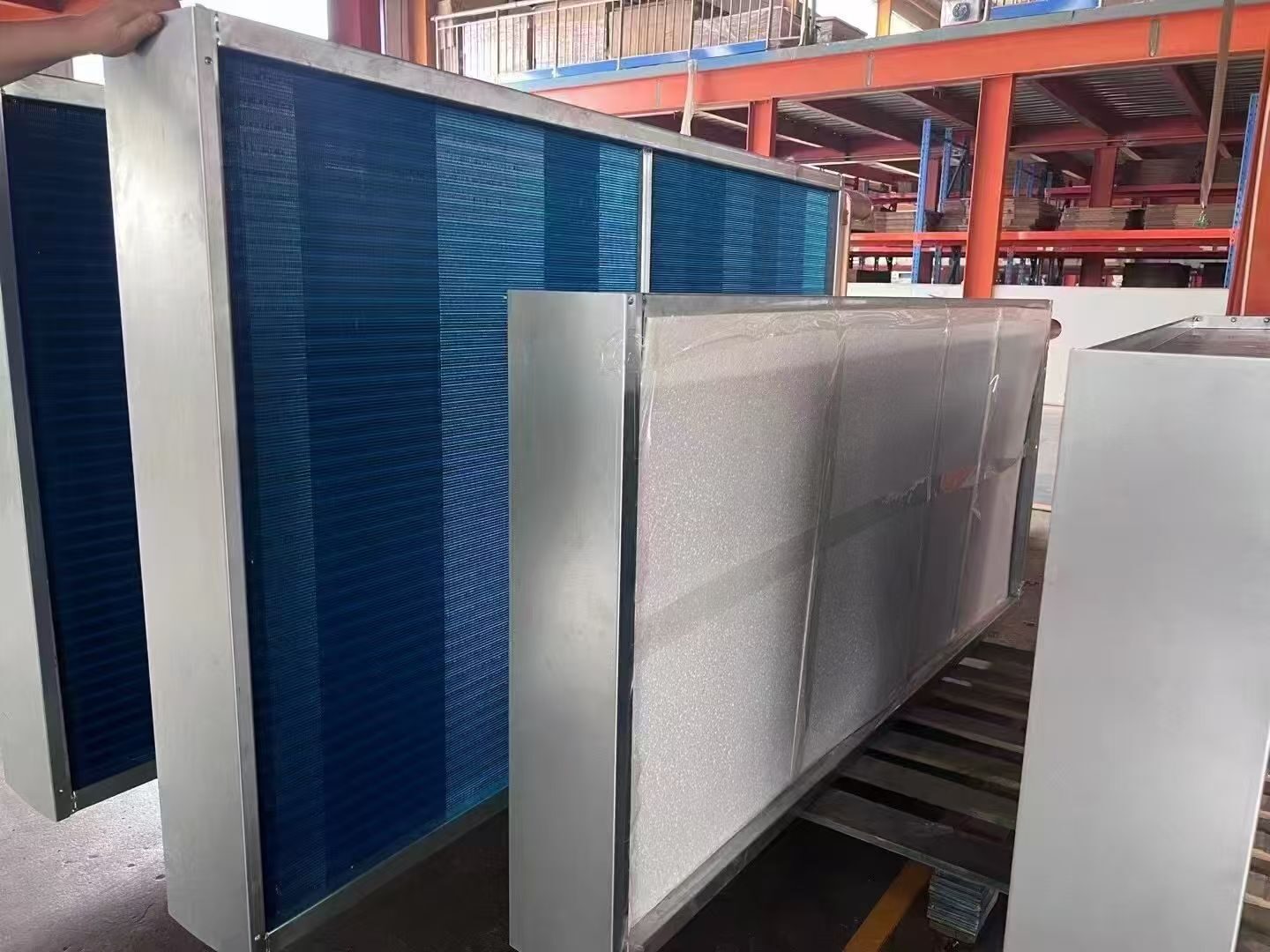
The moisture balance gives a required humidity ratio. Next calculate the air temperatures and energy changes needed to reach it.
Continuing the same fictional example, retain the 1,200 kg/hour dry-air flow and assume atmospheric pressure of 101.325 kPa. Add 30°C outdoor dry-bulb temperature, an idealized nearly saturated coil leaving state of 8.8°C at 7 g/kg, and reheating to 18°C. Assume no fan or duct heat gain between these listed states. Real coil selection must establish an achievable leaving state and account for those gains.
The properties below use the usual perfect-gas HVAC relationships documented in ASHRAE’s psychrometrics chapter. The numerical implementation was checked against the PsychroLib property equations.
REFERENCE TABLE · Scroll horizontally on smaller screens to read all columns.
| State | Dry-bulb temperature | Humidity ratio | Dew point, approximately | Relative humidity, approximately | Enthalpy |
|---|---|---|---|---|---|
| Outdoor air | 30°C | 18 g/kg | 23.2°C | 67.1% | 76.20 kJ/kg dry air |
| Leaving the cooling process | 8.8°C | 7 g/kg | 8.7°C | 99.6% | 26.47 kJ/kg dry air |
| After reheat, supplied to the room | 18°C | 7 g/kg | 8.7°C | 54.6% | 35.85 kJ/kg dry air |
| Target room state | 24°C | 10 g/kg | 14.0°C | 53.7% | 49.60 kJ/kg dry air |
Notice the two different conclusions in this table. The room and reheated supply have similar relative humidities, but the supply contains substantially less water per kilogram of dry air. Meanwhile, reheat changes supply relative humidity from about 100% to 55% without changing its 7 g/kg moisture content or 8.7°C dew point.
At this pressure, air at 9 g/kg has a dew point of about 12.5°C. The earlier comparison therefore shows why a unit selected to supply roughly a 12.5°C dew point would miss the assumed room moisture duty even if its ventilation airflow were correct.
How Do Air Enthalpies Determine Coil and Reheat Duty?
For the stated temperature range, the commonly used approximate enthalpy relationship is:
h = 1.006 x T + W x (2,501 + 1.86 x T)

h: kJ/kg dry air
T: deg C
W: kg water/kg dry air
Convert the dry-air flow to kilograms per second, then use the entering and leaving enthalpies:
Dry-air mass flow = 1,200 / 3,600 = 0.3333 kg/s

Air-enthalpy cooling duty ~= 0.3333 x (76.20 - 26.47)
                          ~= 16.6 kW

Reheat duty ~= 0.3333 x (35.85 - 26.47)
            ~= 3.1 kW
The cooling figure is the air-enthalpy difference, before a small correction for liquid condensate leaving the process. At the assumed 8.8°C drain-water temperature, the 13.2 kg/hour condensate carries about 0.135 kW of liquid-water enthalpy relative to 0°C; subtracting it gives approximately 16.44 kW of heat removed by the coil in this idealized balance. Fan heat and other actual gains belong in the final equipment calculation.
The 3.1 kW reheat requirement is a thermal duty, not automatically 3.1 kW of purchased electrical input. Electric resistance, hot water and recovered refrigerant heat have different plant-energy consequences. Compare the complete proposed system and its control sequence rather than treating recovered heat as a guarantee of zero additional energy use.
Why Can Intake and Supply Airflow Readings Differ?
At the assumed final supply state, specific volume is about 0.834 m³/kg dry air. The 1,200 kg/hour mass flow therefore corresponds to approximately 1,001 m³/hour of actual supply air. The same dry-air mass at the outdoor state occupies approximately 1,060 m³/hour.
These figures are consistent, not evidence of a 59 m³/hour leak. Temperature and moisture content change air volume. Specify whether the scheduled flow is actual volume at a stated condition or a standardized flow, and convert measured volume to dry-air mass before using the moisture balance. This matters when intake and supply measurements are compared during commissioning.
Does Energy Recovery Reduce Dehumidification Load?
An upstream recovery device changes the coil calculation only to the extent that it changes the actual entering air state. Sensible-only recovery can lower entering dry-bulb temperature without lowering humidity ratio. A device that transfers moisture can change both. Eurovent’s AHU quality recommendation distinguishes recovery arrangements and discusses internal air leakage; do not treat recovered energy and cross-stream leakage as interchangeable mechanisms.
In this fictional recovery example, use equal dry-air mass flow on the supply and exhaust sides. Assume the exhaust stream is at the 24°C, 10 g/kg room state, sensible effectiveness is 0.60, moisture effectiveness is 0.50, and there is no leakage or carryover:
Coil-entering temperature = 30 - 0.60 x (30 - 24) = 26.4 deg C
Coil-entering humidity ratio = 0.018 - 0.50 x (0.018 - 0.010)
                            = 0.014 kg/kg
The coil-entering enthalpy becomes approximately 62.26 kJ/kg dry air. With the same leaving condition:
Coil condensate = 1,200 x (0.014 - 0.007) = 8.4 kg/hour
Air-enthalpy cooling duty ~= 0.3333 x (62.26 - 26.47) = 11.9 kW
The air-enthalpy cooling duty falls from 16.6 to 11.9 kW, but the required supply dryness remains 7 g/kg because the assigned room load and delivered mass flow have not changed. The earlier 13.2 kg/hour is therefore not the coil condensate rate in this recovery arrangement.
Check balanced and unbalanced airflow, the required separation of exhaust and supply streams, leakage/carryover data, fan pressure penalties, and the proposed bypass or frost-control modes. Those conditions can change both useful recovery and the coil’s entering state. Include casing leakage and recovery section checks when the proposed unit is assembled on site.
Critical Zone Check: Why Averages Hide Wet Rooms
A central system serving several rooms cannot always use the total building moisture load divided by total airflow as its final dryness target. The critical zone is the one requiring the driest supply after accounting for its allocated airflow and other moisture-removal equipment.
In this fictional two-zone variation, retain the same total load and flow and a 10 g/kg target in both zones:
REFERENCE TABLE · Scroll horizontally on smaller screens to read all columns.
| Zone | Delivered dry-air flow | Assigned room moisture | Required supply humidity ratio |
|---|---|---|---|
| A | 900 kg/hour | 2.1 kg/hour | 0.010 – 2.1/900 = 7.67 g/kg |
| B | 300 kg/hour | 1.5 kg/hour | 0.010 – 1.5/300 = 5.00 g/kg |
| Combined arithmetic | 1,200 kg/hour | 3.6 kg/hour | 7.00 g/kg |
Supplying both at 7 g/kg removes only 300 x (0.010 – 0.007) = 0.9 kg/hour from zone B at its target condition. Its assigned load is 1.5 kg/hour, leaving a 0.6 kg/hour deficit despite a balanced aggregate calculation.
The engineering options are different: provide a drier common supply, allocate more dry air to B, reduce its uncontrolled moisture sources, or assign the remaining duty to local equipment. At 7 g/kg supply, B would need 1.5/(0.010 – 0.007) = 500 kg/hour of dry air to remove that full load. Any airflow change must also satisfy the ventilation, room-pressure, acoustic and sensible-cooling constraints. Resolve the zone allocation before selecting the central unit.
Check the treatment limit before choosing the first option. At the assumed pressure, 5 g/kg corresponds to a dew point near 3.9°C. A conventional cooling-only coil supplied with 7°C water cannot create that dew point using that water alone. The duty allocation, available cooling temperature or treatment method would need to change. This is a concrete reason to complete the zone calculation before selecting the central coil.
Humidity Control on Mild, Rainy Days
The highest outdoor dry-bulb temperature is not necessarily the most revealing humidity-control test. A mild, wet period can impose moisture removal while the rooms need little sensible cooling. If cooling output falls only in response to room temperature, the required supply-air dryness may be lost.
Ask the supplier to return a selection for the peak cooling condition and for a credible low sensible-load, high-moisture condition. Define these from the project’s weather and operating information rather than adopting an arbitrary percentage of peak load.
For each condition, request the actual airflow, entering-air state, coil leaving-air state, final supply-air state and electrical or water-side duty. The controls narrative should explain:
- Which measurement governs dehumidification and where that sensor is located.
- How the required dryness is maintained as cooling demand and airflow change.
- How any reheat responds to the final supply-temperature requirement.
- What happens at the equipment’s minimum controllable output or an unavailable utility condition.
Include the chilled-water conditions for a hydronic coil or the declared operating limits for a refrigerant system. A promised supply dew point is useful only when the selected equipment can maintain it at the stated conditions.
The supply dew point is not the chilled-water temperature or refrigerant evaporating temperature. Heat-transfer approach, coil geometry, air velocity, water flow and surface wetness separate those quantities. Request the manufacturer’s wet-coil selection, including leaving dry-bulb temperature, leaving humidity ratio, water-side duty, air pressure loss and condensate-handling limits. Adding coil rows or reducing face velocity can change pressure losses and physical size as well as leaving condition.
Separate the humidity loop from the final supply-temperature loop. A useful operating description first maintains the required dryness within the equipment’s limits, then adjusts any reheat to the permitted delivery temperature. Sensor positions, fan heat and mixing sections must match the states being controlled. If the required dryness cannot be achieved, the system needs an actionable deviation alarm; reheating wetter air to produce a lower relative-humidity display does not solve that failure.
Where fresh air is delivered through or alongside room fan coil units, check the combined room sensible duty. Cold, dry ventilation air may contribute useful cooling during some hours and require temperature adjustment during others. Use the room balance to decide the reheat sequence, and coordinate it with hotel fan coil selection.
In the worked example, 18°C supply entering a 24°C room contributes approximately 2.04 kW of sensible cooling, using the moist-air heat capacity at 7 g/kg. If the sensible load assigned to this airstream falls to 1.20 kW, a balance with no other heat gains would require supply nearer 20.5°C, while retaining the same 7 g/kg dryness. That is a reason to consider a bounded supply-temperature reset; a fixed 18°C setting is not automatically appropriate throughout the year.
Troubleshooting: Why Rooms Stay Humid with Fresh Air
Begin with simultaneous measurements. Record temperature and humidity at the outdoor intake, after any recovery stage, after the cooling coil, at final supply and in the affected room. Record airflow, room operating conditions and the current control outputs. Check sensor accuracy before interpreting a small difference between readings.
Convert the measurements to humidity ratio or dew point at the relevant pressure. Then follow the branch that matches the evidence:
REFERENCE TABLE · Scroll horizontally on smaller screens to read all columns.
| Observation | Next investigation |
|---|---|
| The coil leaving air is wetter than the selected duty | Compare actual entering conditions and airflow with the selection; check available cooling, water or refrigerant conditions, bypass and control response |
| Coil leaving air is sufficiently dry, but air delivered to the room is wetter | Investigate downstream mixing, leakage, unintended air connections or an unaccounted moisture source along the delivery path |
| Delivered air is dry enough, but its airflow is below the design duty | Check balancing, pressure losses and fan operation; recalculate the moisture removal at the measured dry-air flow |
| Supply dryness and flow both match, but the room is still humid | Revisit the assigned room load, exhaust balance, infiltration, transfer air and transient moisture storage |
| Humidity is acceptable but the room becomes too cold | Check the sensible balance and delivery-temperature control while retaining the required ventilation and dryness |
Avoid responding to a humid-room complaint by simply increasing nominal airflow. The equipment must still achieve the necessary leaving condition at the revised flow, and the building’s ventilation and pressure requirements must remain satisfied. Likewise, reducing required ventilation to hide an overcooling problem does not resolve the design duty.
What to Include in a FAHU Specification
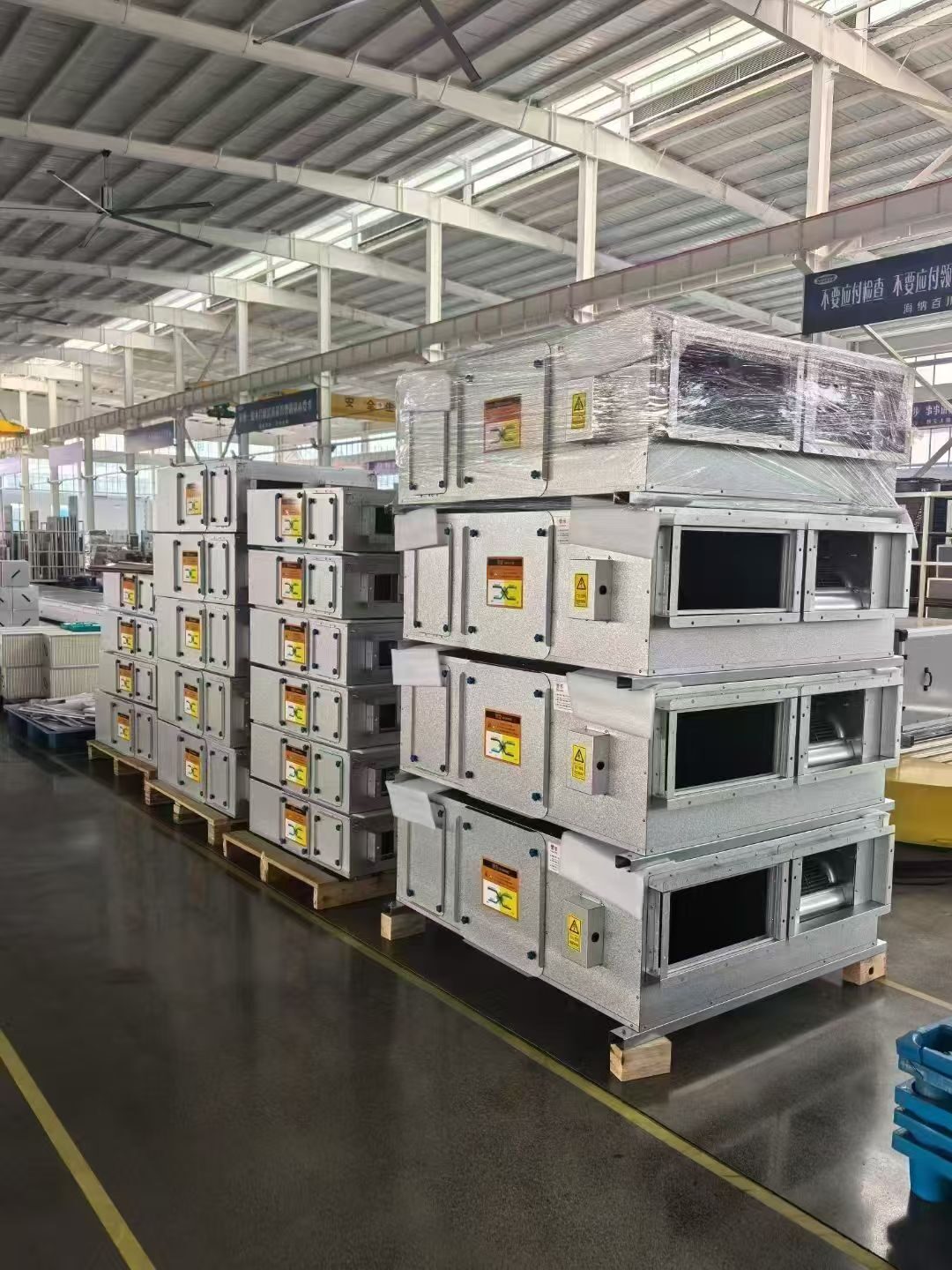
A useful enquiry identifies outdoor design states, ventilation flow, the room humidity target, assigned room moisture load, supply-air dryness, final supply temperature and available utilities. It also identifies which equipment owns any remaining room load. Without those responsibilities, two suppliers may return different scopes while appearing to quote the same airflow.
For acceptance, agree a trend period that includes representative occupied and low-load conditions. Record supply dryness and airflow together with room temperature and humidity. A spot check at one convenient outdoor condition cannot establish seasonal humidity performance.
Frequently Asked Questions
What supply dew point should a DOAS deliver?
It depends on the assigned room moisture load and delivered dry-air mass flow. Required supply humidity ratio = room humidity ratio – (moisture load / dry-air flow). In this guide’s example, 10 g/kg room air, 3.6 kg/hour moisture and 1,200 kg/hour dry air require 7 g/kg supply air, or about 8.7°C dew point at 101.325 kPa.
Does reheat remove moisture?
No. Reheat raises temperature and lowers relative humidity without changing humidity ratio or dew point. In the example, reheating from 8.8°C to 18°C leaves the supply at 7 g/kg.
Can a 7°C chilled water coil supply very dry air?
The required dew point sets the limit. At the pressure used here, air at 5 g/kg has a dew point near 3.9°C. A conventional cooling-only coil supplied with 7°C water cannot reach that condition using that water alone.
What is the difference between a FAHU and an AHU?
A FAHU is an air handling unit configured to treat 100% outdoor air for ventilation. An AHU may instead mix return and outdoor air, or serve an all-outdoor-air duty. Whether the FAHU also removes room moisture depends on the assigned duty and how dry its supply air is.
Provide that design brief with a SongXin project enquiry. Request the selection at the stated conditions and the sequence that maintains them, so the resulting fresh air system has a defined moisture-control duty as well as a ventilation capacity.