Hotel Fan Coil Unit Selection: Capacity, Noise & ESP
Technical guide · September 30, 2026
A hotel fan coil should meet the guest room’s cooling requirement at a fan setting that also satisfies its acoustic requirement and the resistance of the installed air path. A high-speed cooling rating combined with a low-speed noise figure does not demonstrate that the unit can do both at once.
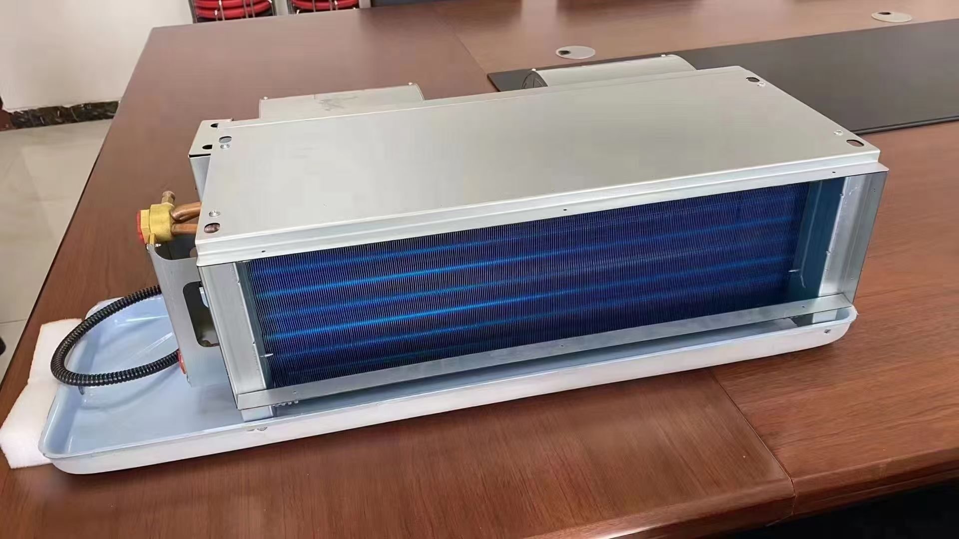
For a concealed ducted fan coil unit, request one coordinated selection for each important room operating condition. It should show sensible and total cooling, airflow, external static pressure (ESP), water conditions and sound data at the same fan speed or control setting. The ceiling layout and air outlets then need to support that selection.
This article focuses on hydronic fan coils, particularly concealed ducted units used in hotel guest rooms. SongXin offers both fan coil units and concealed FCUs; the final type and configuration should follow the room requirements below.
Key takeaways
- Cooling capacity, airflow, ESP and noise must come from the same fan setting. A high-speed capacity paired with a low-speed noise figure does not establish a usable operating point.
- Check sensible and latent capacity separately; a unit can pass on total kW and still fail moisture removal.
- Catalogue sound power is not guest-room sound pressure. Two independent 28 dB(A) contributions at the same receiver combine to about 31 dB(A).
- A unit sized for peak load can still leave rooms humid on mild nights. Assign that moisture duty explicitly to the ventilation system, the room equipment or both.
About the examples in this guide: All numbers in the worked examples are fictional assumptions chosen to demonstrate the method. They are not typical values, design allowances, or measured SongXin performance. Use the selected equipment’s data and your project conditions for any real decision. In formulas, x means multiplication and ~= means approximately equal.
What Operating Modes Should a Hotel FCU Selection Cover?
A room can have more than one legitimate cooling duty. An unoccupied room recovering from a warm setback may permit a different fan setting from an occupied bedroom at night. Make that distinction explicit instead of asking one unspecified “quiet” mode to cover every situation.
For each room type, establish:
- The sensible and latent loads, indoor design temperature and humidity requirement.
- The entering chilled-water temperature, design water flow and return-water basis.
- The ventilation arrangement, including where treated outdoor air enters the room.
- The intended occupied and recovery modes, together with the fan settings allowed in each.
- The acoustic criterion, measurement location and operating condition used for acceptance.
Check at least one demanding occupied condition as well as any required recovery condition. If the design allows a louder recovery mode only before check-in, that mode cannot be used to demonstrate occupied-room compliance.
Keep the ventilation duty separate from the FCU’s recirculating airflow. Identify which equipment removes moisture from outdoor air and which removes moisture generated in the room. This establishes the duty left for the fan coil; it also prevents a large recirculating airflow figure from being mistaken for adequate ventilation. See how to size fresh air for moisture removal before assigning the FCU latent load.
How to Calculate FCU Airflow from Room Load
First translate the room requirement into an air-side duty. This gives you a way to challenge a selection that lists an attractive kW rating but does not show how that cooling reaches the room.
What Airflow Does the Sensible Load Require?
For a first sensible-cooling check near ordinary room conditions, use the approximate volumetric heat capacity of air, 1.2 kJ/(m³·K):
Sensible cooling, kW ~= 1.2 x airflow, m^3/s x (room temperature - supply temperature), KIn this fictional room example, the room needs 2.4 kW of sensible cooling at 24°C, with 14°C air delivered at the room outlet:
Required airflow ~= 2.4 / [1.2 x (24 - 14)]
                 = 0.20 m^3/s = 720 m^3/h
If the delivered air were 16°C instead, the same calculation gives 900 m³/h: 25% more airflow. That change affects the fan selection, duct resistance and outlet performance. Assess the outlet’s throw, occupied-zone air speed, condensation risk and room layout before setting the delivery temperature.
Use the temperature at the room outlet in this room balance. A coil leaving-air temperature can be colder because fan heat and duct heat gain may occur before delivery. For final selection, use the actual moist-air properties and air state; the approximation above establishes the order of magnitude.
Now add the latent requirement. If the room also has a 0.6 kW latent load, its required sensible heat ratio is:
Required sensible heat ratio = sensible load / total load
                            = 2.4 / (2.4 + 0.6) = 0.80
A unit delivering 3.2 kW total but 2.9 kW sensible has only 0.3 kW latent capacity at that point. It passes a total-kW comparison while failing the stated moisture duty. Request the coil selection at the actual entering dry-bulb and wet-bulb temperatures, water conditions and fan setting. The capacity split is a result of those conditions, not a fixed percentage that can be carried into every operating mode.
Why Catalogue Capacity and Noise Figures Don’t Match
The Eurovent fan coil programme distinguishes sensible capacity, total capacity, airflow, available pressure and sound power at different speeds. Those distinctions are useful even when the offered model is outside that programme: each number needs an operating condition, and any certification claim needs to match the exact offered model.
For a room with separate sensible and latent requirements, compare both capacity components. A total cooling figure that exceeds the combined load can still conceal insufficient sensible capacity. Conversely, meeting the sensible load does not establish that moisture control is adequate.
Manufacturer schedules may state cooling capacity at high speed while listing sound data at high, medium and low speed. Check the rating notes and acoustic measurement location. Selecting the largest cooling number and the smallest sound number can create an operating point the schedule has not demonstrated.
Ask for a project-specific selection at the actual water and entering-air conditions. A standard catalogue rating is a reference point, rather than confirmation of performance in a different room or water system.
How Much ESP Does a Ducted Fan Coil Need?
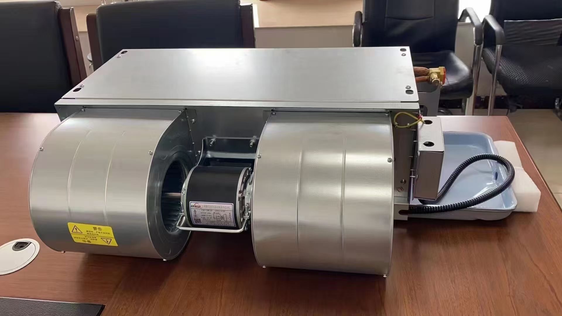
For a ducted FCU, the selected fan must deliver the required airflow through the connected supply and return air paths. Define which losses are inside the unit’s rating and which must be included in the external static pressure requirement.
Prepare a short pressure schedule for the critical air path. Include the relevant duct lengths and fittings, supply outlets, return arrangement and any external accessories. Record how the installed filter is treated. A filter or plenum already included in the unit selection should not be added a second time; an external component omitted from that selection still needs to be counted.
In this fictional pressure example, the project team calculates:
REFERENCE TABLE · Scroll horizontally on smaller screens to read all columns.
| External item at the design airflow | Assumed pressure loss |
|---|---|
| Supply duct and fittings | 22 Pa |
| Supply outlet | 18 Pa |
| External return path and grille | 15 Pa |
| Explicit design allowance | 5 Pa |
| Required external static pressure | 60 Pa |
The external pressure total is 22 + 18 + 15 + 5 = 60 Pa. The FCU’s internal coil and filter losses are assumed to be included in the supplier’s selection and are not added here.
A selection at 30 Pa is not proof of the required airflow at 60 Pa. Return it for reselection at the stated duty. If the chosen fan setting cannot deliver the airflow, the useful options are to reduce external resistance, change the fan or unit selection, or revise the permitted operating setting and recheck noise.
How Do Fan and System Curves Set Actual Airflow?
The operating airflow is where the pressure available from the fan/unit matches the connected system’s pressure requirement. The guide to fan performance tables and curves explains how the fan and system curves establish that operating point.
In this fictional curve example, use a fixed-speed external-pressure curve and a quadratic external-system curve:
Available external pressure = 100 - 40 x (airflow / 720)^2, Pa
Required external pressure = 60 x (airflow / 720)^2, Pa
Airflow is in m^3/h.
REFERENCE TABLE · Scroll horizontally on smaller screens to read all columns.
| Airflow | Available pressure | Required pressure | Interpretation |
|---|---|---|---|
| 600 m³/h | 72.2 Pa | 41.7 Pa | More pressure is available than this path requires at that flow |
| 720 m³/h | 60.0 Pa | 60.0 Pa | Curves intersect at the intended duty |
| 840 m³/h | 45.6 Pa | 81.7 Pa | This fan setting cannot sustain the proposed flow |
The quadratic approximation describes predominantly frictional resistance over a relevant range, not every damper, filter or control system at every setting.
Suppose an external filter or accessory changes the assumed system coefficient from 60 to 80 Pa at 720 m³/h. Equating the revised curves gives:
100 - 40 x (airflow / 720)^2 = 80 x (airflow / 720)^2
New airflow = 720 x sqrt(100 / 120) ~= 657 m^3/h
At the unchanged fan setting, airflow falls by about 8.7%. Cooling capacity must be reselected at that point; it should not simply be reduced by the same percentage. If an EC controller instead maintains airflow, verify the new speed, power and sound output. An EC motor does not necessarily include constant-airflow control, and additional available speed does not establish that the acoustic requirement still passes.
Include the agreed filter-loading condition in the pressure schedule. A clean-filter selection and a loaded-filter acceptance requirement describe different duties. If the filter is inside the supplier’s selection boundary, require both conditions there rather than adding its loss again as an external item.
Fan Coil Noise: Sound Power vs Room Sound Pressure
Sound power characterizes the acoustic output of the source under stated test conditions. Sound pressure describes the sound at a receiving position and depends on the path and surrounding environment. Brüel & Kjær explains this fundamental distinction in its introduction to noise measurement parameters. A catalogue sound-power value therefore cannot be compared directly with a bedside sound-pressure limit, even if both are written in dB(A).
For concealed units, ask the acoustic review to distinguish sound entering the supply duct from sound radiated through the casing and return path. A short, open return above a bedroom ceiling can require a different treatment from a fully ducted return. Supply outlets and water-control components also need consideration in the completed room.
The submission should identify:
REFERENCE TABLE · Scroll horizontally on smaller screens to read all columns.
| Acoustic item | Evidence needed |
|---|---|
| Equipment source | Sound-power data at the selected fan setting, with the test method identified |
| Transmission paths | Supply duct, return path, casing radiation and relevant building construction |
| Room criterion | Agreed metric, limit, location and occupied operating condition |
| Predicted result | Calculation using the proposed room and installation, including its assumptions |
| Acceptance result | Measurement in a completed mock-up room under the agreed conditions |
Where frequency-dependent assessment is required, request octave-band data rather than relying only on one overall number. Record whether a quoted room result is a prediction or an actual measurement. Neither an unexplained “low noise” description nor a bare decibel value is sufficient for acceptance.
In this fictional sound example, for two independent contributions of 28 dB(A) each at the receiver, logarithmic addition gives approximately 31 dB(A), not 28 dB(A):
Combined level = 10 x log10[10^(28/10) + 10^(28/10)] ~= 31.0 dB(A)This example assumes the contributions refer to the same receiver, metric and operating condition and are uncorrelated. The addition principle is explained in Brüel & Kjær’s environmental noise guide. It shows why separately acceptable contributions can fail when combined. For tonal, correlated or frequency-dependent sound paths, perform the appropriate acoustic assessment; a single overall value can hide an objectionable frequency component.
Acoustic treatment must also be coordinated with airflow. An attenuator can add resistance; a smaller grille may increase local velocity; a larger access opening can change the return sound path. Recalculate the selected operating point after those changes. During the room test, record background sound with the FCU off and apply the agreed measurement method’s background correction and validity rules.
Worked Example: Which Hotel FCU Submission Meets the Duty?
In this fictional selection comparison, the guest room needs 2.4 kW sensible cooling and 0.6 kW latent cooling, for 3.0 kW total, at its designated occupied condition. Its external pressure requirement is 60 Pa. The project has also chosen a maximum occupied-mode level of 30 dB(A) at a defined receiver position.
Assume the figures below use the same room and water conditions where those conditions are supplied, with capacities expressed net at the same unit boundary. The room sound-pressure predictions use the same agreed calculation method and room model.
REFERENCE TABLE · Scroll horizontally on smaller screens to read all columns.
| Submission | Cooling evidence | Pressure evidence | Acoustic evidence | Review decision |
|---|---|---|---|---|
| A | 3.6 kW total and 2.7 kW sensible at high speed | Rated at 30 Pa | 28 dB(A) predicted at low speed | Incomplete: capacity, pressure and noise do not describe the required operating point |
| B | 3.2 kW total and 2.5 kW sensible at medium speed | Required airflow at 60 Pa | 31 dB(A) predicted at the same setting | Cooling and pressure fit the stated duty; the predicted room result exceeds the assumed acoustic limit |
| C | 3.3 kW total and 2.6 kW sensible at a declared variable-speed setting | Required airflow at 60 Pa | 29 dB(A) predicted at the same setting | A coordinated candidate for the remaining checks and mock-up room verification |
Submission C has an implied latent capacity of 3.3 − 2.6 = 0.7 kW, exceeding the assumed 0.6 kW requirement at this condition. That does not establish all-weather humidity control; the low sensible-load condition still needs assessment with the ventilation strategy.
For A, request one corrected selection rather than rejecting the product on incomplete information. For B, investigate whether the acoustic path or unit selection can be improved while preserving the required duty. If adding an attenuator changes resistance, revise the fan selection and acoustic prediction together.
C can move forward because the evidence is internally consistent. It still needs a workable water circuit, drain arrangement, physical installation and acceptance test.
Why Hotel Rooms Feel Humid at Part Load
The occupied summer selection does not answer what happens on a humid night with little solar or envelope load. In this fictional part-load example in the same room, sensible load falls to 0.8 kW while latent load remains 0.6 kW. The required sensible heat ratio is now about 0.57, compared with 0.80 at the original condition.
For a deliberately simplified on/off example, suppose submission C delivers its original 2.6 kW sensible and 0.7 kW latent output whenever enabled, and the room-temperature controller alone determines run time:
Sensible-load runtime fraction = 0.8 / 2.6 ~= 0.308
Average latent removal = 0.7 x 0.308 ~= 0.215 kW
Latent shortfall ~= 0.6 - 0.215 = 0.385 kW
This example assumes immediate steady output during each on-cycle and no off-cycle moisture return. Actual modulating coils need selection at their part-load conditions because their capacity split changes. Adequate peak latent capacity does not establish part-load humidity control.
Resolve the duty with the ventilation design. A dedicated outdoor-air system can supply air dry enough to remove an assigned share of room moisture; otherwise the terminal system needs a demonstrated humidity-control strategy. Changing fan speed, water temperature or valve position alters coil performance and must be checked at the resulting condition. Oversizing the nominal FCU alone does not establish the required moisture removal. Follow the moisture balance for specifying the supply air dew point when allocating that duty to fresh air.
FCU Water Flow, Fan Heat and Control Valve Sizing
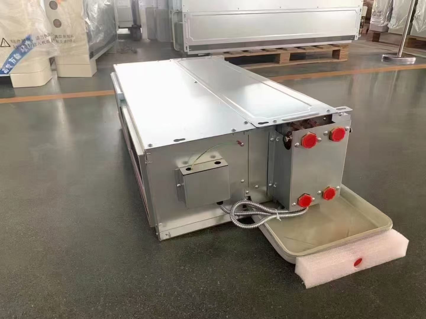
Confirm whether quoted cooling capacities are gross coil values or net unit values. Submission C’s 3.3 kW net corresponds to about 3.35 kW gross coil duty if 50 W of fan heat enters the airstream. The gross-to-net difference affects sensible and total cooling; it does not become extra latent capacity. Ask the supplier to state its rating convention and the location of the fan.
Continuing submission C’s fictional example, use its 3.35 kW water-side duty with water at 7°C entering and 12°C leaving:
Water mass flow = 3.35 / [4.18 x (12 - 7)] ~= 0.160 kg/s
Volume flow ~= 0.577 m^3/h, using water density of 1,000 kg/m^3
Obtain the actual coil selection and its pressure loss at the calculated water flow. If entering water becomes warmer, do not retain the original kW and latent values without reselection.
Next compare the complete branch pressure budget. Assume 15 kPa through the coil, 10 kPa through the selected control valve and 8 kPa through the remaining branch components. The circuit needs 33 kPa at that flow. If only 28 kPa is available between the branch connections, the design point has a 5 kPa shortfall.
Making the control valve larger may reduce pressure loss but can weaken modulation. The valve application guide explains how series resistance and changing available pressure affect valve authority. If the simplified circuit above were provided with its required fixed 33 kPa, the authority estimate would be 10/33, or about 0.30.
Request a valve and actuator selection that accounts for available differential pressure over the operating range, controllable minimum flow and shutoff conditions. A pressure-independent valve also has a required operating pressure range; it cannot compensate for an inadequate available head. Agree how balancing and control will be verified before approving a repeated room detail.
Ceiling Access and Condensate Drainage
Place the FCU, valve package, drain arrangement, access panel and ducts on one coordinated drawing. Confirm that the filter can be removed and that the fan, controls and valves can be serviced without dismantling permanent finishes. Include the removal path for the largest component expected to be replaced.
Where the design uses a condensate pump, account for its access and operating noise. Where it uses gravity drainage, confirm the actual route and height needed for the selected arrangement. These decisions should appear on the drawing before ceiling space is committed to lighting and other services.
Mock-Up Room Testing Before Hotel Rollout
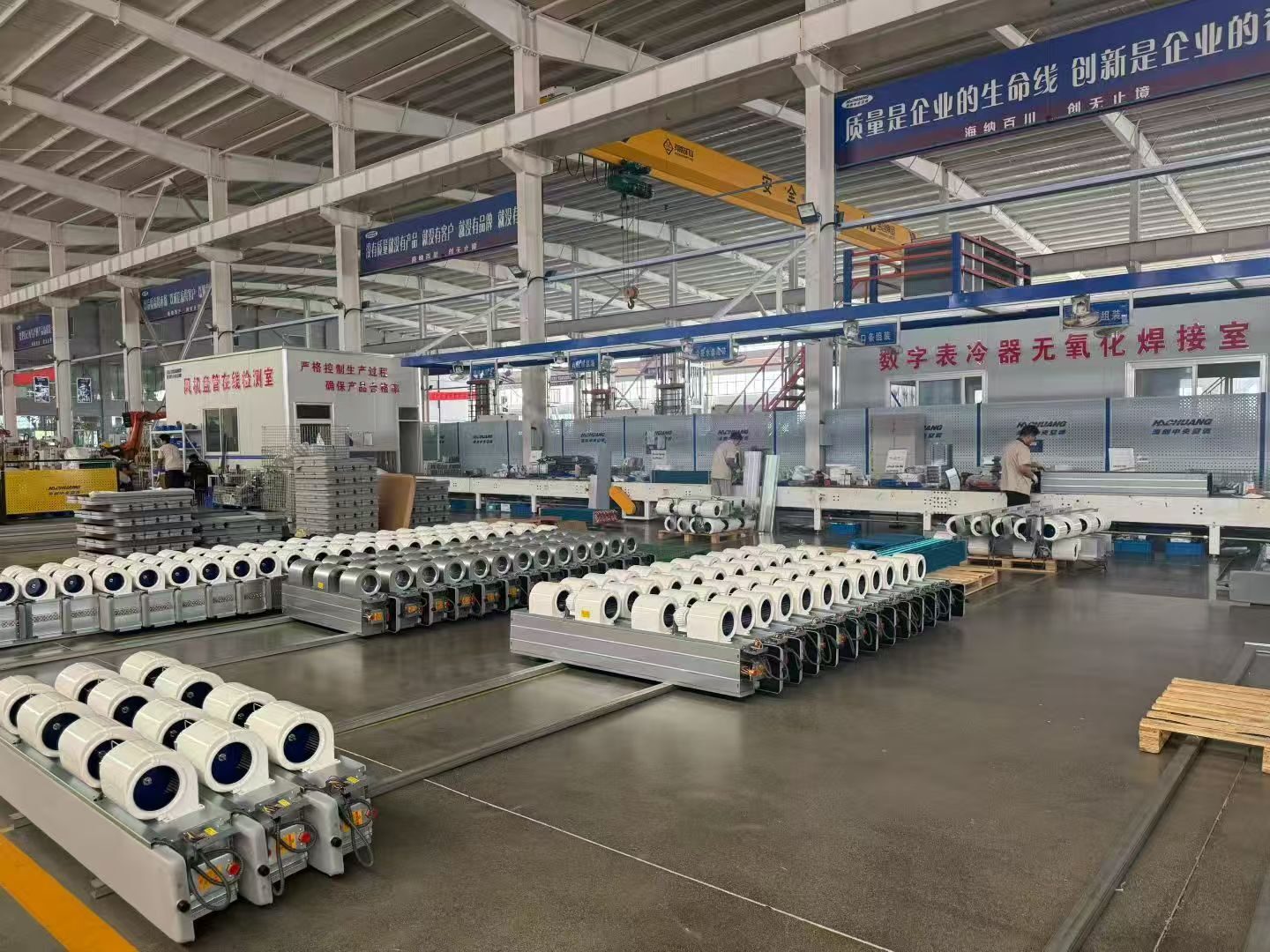
Before repeating a guest-room detail across a large hotel, test a full mock-up room with the intended ceiling, return path, supply outlets and controls. Record airflow, fan setting, water temperatures and room conditions alongside the acoustic test. A quiet room measured while the FCU is delivering less than the required airflow is not evidence that the intended operating point passes.
Use the following questions to close the selection:
- Does the occupied-mode selection meet sensible and latent duties at the scheduled water conditions?
- Is its airflow demonstrated at the calculated external pressure?
- Does the acoustic prediction use that same fan setting and the actual room construction?
- Can the unit, filter, valves and drain be maintained through the proposed access?
- Does the mock-up room result confirm the agreed thermal, airflow and acoustic requirements together?
Frequently Asked Questions
What external static pressure does a hotel ducted FCU need?
Add the supply duct, outlets, return path and external accessories at design airflow, counting each loss once. The example totals 60 Pa; a selection rated at 30 Pa must be reselected at the required airflow and ESP.
What noise level should a hotel room fan coil achieve?
Use the project’s acoustic brief, with a defined receiver position, metric and occupied fan setting. A catalogue dB(A) value alone cannot demonstrate compliance. The 30 dB(A) limit in the example is a project assumption.
Why is my hotel room humid when the FCU is big enough?
At low sensible load, temperature-controlled operation may run less and remove too little moisture. Check the FCU at part load and confirm the dryness and mass flow of the fresh air. The moisture duty must be met by the ventilation system, local equipment or their combined output.
Are FCU capacities gross or net?
Either convention may be used. Ask which one applies: fan heat entering the conditioned air reduces net sensible and total cooling. In submission C’s example, 3.35 kW gross less 50 W fan heat gives 3.30 kW net.
For a SongXin enquiry, provide the room-type schedule, cooling loads, water conditions, ceiling section, external pressure calculation and acoustic brief through the project quotation page. Request a coordinated selection for each room type so the final decision rests on a usable operating point rather than unrelated catalogue highlights.