Hotel HVAC · VRF · Selection guide
Heat Recovery VRF vs Heat Pump VRF for Hotels
Start with simultaneous room demand. Then compare system grouping, controls and the complete installed scope.
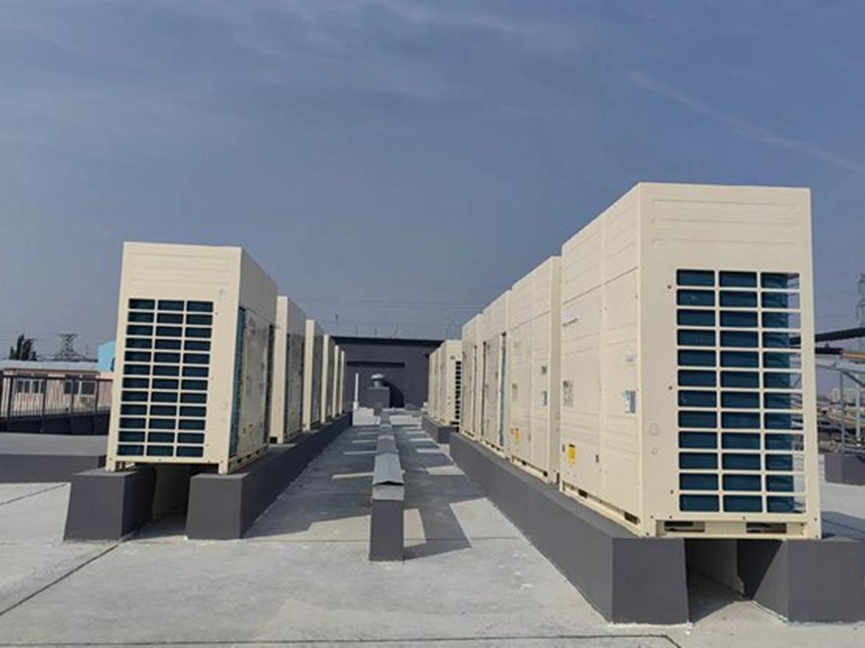
Find opposite room demands on the same circuit.
Confirm supported modes and branch controls.
Compare like-for-like installation and operation.
Choose heat recovery VRF when rooms on the same connected system need heating and cooling at the same time. Consider heat pump VRF when those rooms can use a common operating mode, or when sensible grouping into separate systems resolves their different needs. The useful comparison starts with room demand and controls, not the number of guestrooms or a promised energy-saving percentage.
Key takeaways: map simultaneous loads by refrigerant system; distinguish room temperature control from independent heating/cooling mode; and compare complete installed scope. A two-pipe description does not, by itself, identify a heat-pump-only system—two-pipe heat recovery products also exist.1
Prepared with AI assistance for SongXin HVAC. Draft updated September 9, 2026; human technical review has not yet been completed.
Put opposite room demands on the same timeline
Variable refrigerant flow, or VRF, distributes heating or cooling through a refrigerant network serving multiple indoor units. A conventional heat pump VRF circuit operates in heating or cooling mode at a given time. Heat recovery VRF can serve opposing zone demands simultaneously through its supported refrigerant and branch-control arrangement.2
The key procurement question is: which rooms require opposite modes during the same period, and are they actually connected to the same system? A hotel-wide total can conceal the answer. Heating in one independently served wing and cooling in another does not automatically justify replacing both with heat recovery equipment.
Ask the designer to produce a zone schedule with room use, orientation, occupancy and the intended indoor-unit grouping. Identify the shared outdoor system for each group. If a bedroom, meeting space and internal support room require conflicting modes, show how the proposed controls will respond.
Record the timing of each zone, not just its room label
Use this proposed worksheet for hotel guestrooms, meeting areas and administrative offices. Complete it with the project’s actual schedules and designer-calculated loads. The room descriptions below do not imply a particular heating or cooling demand.
| Zone group to document | Schedule or control question | Evidence to put on the system drawing |
|---|---|---|
| Guestrooms with different exposure | Which occupied periods require opposite modes, and what control does each guest retain? | Room IDs, time-aligned loads and assigned refrigerant circuit |
| Meeting rooms and public areas | How do event schedules, vacancy settings and conditioning periods interact? | Operating schedule, required modes and control priority |
| Administrative offices or separately operated space | Who controls occupied hours, overrides and access for maintenance? | Responsible operator, agreed schedule and system boundary |
Review conflicts within each proposed circuit before comparing hotel-wide totals. If different operating responsibilities make a shared arrangement unsuitable, ask for a separately grouped alternative and compare it against the same comfort brief.
Keep space-conditioning selection connected to the broader hospitality HVAC solution. Ventilation, moisture control and domestic hot water must have a defined scope rather than being assumed to follow from the VRF label.
Compare operating modes before comparing pipe counts
Heat recovery describes a function, not one universal piping layout. Schnackel Engineers describes both three-pipe and two-pipe heat recovery arrangements. Mitsubishi Electric’s PURY-EM-TXU provides a manufacturer example of a two-pipe heat recovery network with branch circuit controllers.21
| Architecture described in the cited sources | Main refrigerant-pipe count described | Concurrent heating and cooling within the connected system | What the quotation must identify |
|---|---|---|---|
| Conventional heat pump VRF | 2 | 1 operating mode at a time | Grouping and mode-priority logic |
| Three-pipe heat recovery VRF | 3 | 2 modes can operate concurrently | Branch arrangement and supported combinations |
| Two-pipe heat recovery VRF | 2 | 2 modes can operate concurrently | Compatible branch controller and system design |
Sources: Schnackel Engineers and Mitsubishi Electric.21 Pipe counts describe the cited main-system arrangements; individual branch segments and manufacturer layouts can differ. The table does not identify the configuration of any unspecified SongXin model.
For a project using heat recovery VRF, request the actual piping schematic and indoor-unit combination. The selection report should show how the requested operating modes are available within that combination. A brochure stating “individual control” is not enough if it only refers to separate temperature setpoints.
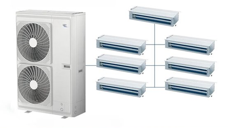
Review heat recovery VRF
Use a load-timing worksheet to reveal the useful overlap
Simultaneous demand creates the opportunity for heat sharing; it does not establish an electricity-saving percentage. Heat removed from cooling zones can contribute to heating zones, but the actual balance depends on compressor work, losses, capacity limits and controls.2
Use the following fictional worksheet to structure a design discussion. All loads and durations are assumed for illustration. They are not measured hotel data, annual simulation results or SongXin performance values.
| Assumed operating period for one connected group | Cooling load | Heating load | Duration | Smaller concurrent load × duration |
|---|---|---|---|---|
| Mixed morning demand | 20 kW | 30 kW | 2 h | 40 kWh thermal |
| Predominantly cooling afternoon | 40 kW | 5 kW | 4 h | 20 kWh thermal |
| Cooling-only evening | 20 kW | 0 kW | 3 h | 0 kWh thermal |
The final column is a load-overlap indicator, calculated as the smaller of the cooling and heating loads multiplied by duration. Its sum is 60 kWh thermal for this constructed schedule. It is neither recovered heat nor avoided electricity, and it is not a thermodynamic limit on heating output because compressor energy also affects the balance.
The worksheet changes the questions asked of the supplier. The afternoon has a larger total load than the morning but much less opposing heating demand. The evening has none. A savings estimate that assumes the same recovery benefit throughout these periods would need justification.
For a real hotel, use the designer’s hourly zone loads or logged operation. Run both proposed architectures against the same weather, occupancy and setpoint assumptions. Record changes to system grouping separately so the comparison does not attribute every benefit to heat recovery alone.
Decide whether the additional scope is worth buying
A heat recovery proposal should show both the comfort function purchased and the expected cost consequence. Consider capital cost, installation, branch-controller access, control integration, maintenance and energy under a common scope. Separate these from any commercial value assigned to room-by-room mode flexibility.
The following cost sensitivity is an arithmetic tool, not a price quotation or a savings forecast. Assume an incremental installed cost of $10,000 and three possible annual net operating savings supplied by a future project analysis.
| Assumed net annual operating saving | Simple payback on the assumed $10,000 premium | Five-year net benefit after the premium |
|---|---|---|
| $1,000/year | 10 years | −$5,000 |
| $2,000/year | 5 years | $0 |
| $4,000/year | 2.5 years | $10,000 |
Simple payback = premium ÷ net annual saving. Five-year net benefit = five times the annual saving minus the premium. Values exclude discounting, price escalation and replacement costs. The annual saving must already include any additional operating and maintenance expenses. At zero or negative net savings, there is no positive simple energy-cost payback.
This calculation deliberately leaves room for a different decision: a hotel may value simultaneous guestroom modes even when energy savings alone do not recover the premium. Record that comfort requirement explicitly rather than inflating the energy estimate to justify it.
Resolve service access and control priority while the design is editable
Locate branch-control equipment on the coordinated drawing. If inspection or replacement would require unacceptable disturbance to an occupied room, change the access arrangement or system grouping before the installation scope is fixed. A technically available function is less useful when normal service cannot be performed within hotel operating constraints.
Define which controller has authority over mode and setpoint requests. Document what happens when guest controls, room-status signals and central commands conflict. The proposed controls should implement the hotel’s operating policy, and the acceptance test should demonstrate that sequence.
Ask for a refrigerant-system schedule identifying model, refrigerant, connected units and calculated charge. Have the project designer evaluate the actual installation under applicable local requirements. Do not substitute a generic pipe-count table or another manufacturer’s product claim for the safety assessment of the proposed system.
Use this decision flow when comparing submissions:
No → Evaluate heat pump VRF with documented mode control. Yes → Check whether regrouping can resolve the conflict.
Yes → Compare regrouped heat pump and heat recovery options. No → Evaluate a compatible heat recovery configuration.
Review controls, service access, installed scope and annual cost on the same design basis.
Figure: hotel VRF selection based on connected-zone demand, acceptable regrouping and complete project scope.
When heat recovery is not the obvious choice
If the hotel includes a server room or other critical technical space, assess its cooling continuity separately before using its load in a heat-sharing proposal. A convenient source of cooling demand does not establish that shared power, controls or maintenance isolation are acceptable. Define the permitted interruption and required remaining service first; then review the proposed connection against that requirement. The server-room cooling selection guide provides the corresponding capacity, operating-envelope and failure-response checks.
Do not specify heat recovery solely because the building is a hotel. If the connected zones share a common mode for the relevant operating periods, a heat pump arrangement may meet the brief. If independent room modes are essential, however, a cheaper same-mode proposal does not offer equivalent functionality.
Also reconsider a proposed arrangement when required equipment access cannot be provided, the local support plan is unclear, or the simulation compares different comfort conditions. First correct the scope or grouping. Avoid turning an unresolved installation problem into an assumed operating benefit.
Put the selection evidence into the RFQ
Ask each bidder for a system-specific response covering:
- Zone schedule, indoor-unit allocation and connected outdoor-system groups.
- Concurrent heating/cooling requirements and the load-analysis basis.
- Proposed model combination, selection conditions and capacity corrections.
- Piping schematic, branch-controller schedule and maintenance access.
- Mode priority, guest control, central control and alarm sequences.
- Ventilation and domestic-hot-water responsibilities and exclusions.
- Commissioning procedure, technical documents, warranty scope and spare-parts proposal.
For supplier evaluation after the architecture is selected, use the separate VRF supplier assessment guide. This keeps supplier capability and system suitability as distinct decisions.
Send your zoning plan, load schedule and installation constraints through SongXin’s request-a-quote page to discuss the equipment scope. Request that alternatives use identical design conditions and clearly list every inclusion and exclusion.
Frequently asked questions
Can heat pump VRF heat one room and cool another simultaneously?
Conventional heat pump VRF does not provide opposite modes simultaneously within the same connected refrigerant system. Separate systems may operate in different modes. For a hotel, identify the actual grouping before deciding that heat recovery is required. Separate setpoints alone do not establish independent heating and cooling mode capability.
Does every heat recovery VRF system use three pipes?
No. Both two-pipe and three-pipe heat recovery arrangements exist. Mitsubishi Electric documents a two-pipe example using compatible branch circuit controllers. Obtain the piping schematic for the exact product and combination being offered. Do not classify an entire system from the visible pipe count at one indoor unit or branch.
Will heat recovery VRF always reduce a hotel’s annual energy cost?
No fixed saving can be established from the system label. The result depends on concurrent zone loads, climate, grouping, controls and equipment performance. Compare both designs under identical conditions and include maintenance differences. Treat independent guestroom mode control as a separate functional benefit when judging the additional installed cost.
Does heat recovery VRF automatically supply hotel hot water?
No. Transferring heat between space-conditioning zones does not automatically provide a domestic-hot-water system. A proposal must explicitly identify any supported water-heating equipment, capacities, temperatures and integration responsibilities. Keep the hotel’s hot-water demand and storage design in the project scope rather than assuming the VRF selection has addressed them.
References
-
Mitsubishi Electric Trane HVAC US, PURY-EM-TXU Heat Recovery High Efficiency Heat Pump, accessed September 9, 2026. Manufacturer evidence for a two-pipe heat recovery configuration with branch circuit controllers; not a specification for SongXin equipment. ↩↩↩
-
Schnackel Engineers, Heat Recovery vs. Heat Pump VRF Systems: What’s the Difference?, accessed September 9, 2026. Used for system modes and two-/three-pipe architecture distinctions; scenario calculations are original illustrations with stated assumptions. ↩↩↩↩